
Combined optical fiber wheel, beamsplitter, switch, and logic gate

a technology of optical fiber wheel and logic gate, which is applied in the field of optical system, optical system, telecommunications, photonics, etc., can solve the problems of increased and unwanted amount of flexure in the optical system, unwanted lengthening of the light path, and increased cost, so as to facilitate optical routing and switching, facilitate optical computation, and facilitate high-resolution imaging and tracking.

Active Publication Date: 2007-10-09
KEYSTREAM LABS LLC
View PDF14 Cites 50 Cited by
  • Summary
  • Abstract
  • Description
  • Claims
  • Application Information

AI Technical Summary

Problems solved by technology

Prior art suffers from a number of disadvantages:(a) different devices are required to be used to perform all of the desired functions;(b) cost is increased when requiring several devices to perform the desired functions;(c) an increased number of devices in an optical system can cause an increased and unwanted amount of flexure in the optical system;(d) an increased number of devices in an optical system can cause an unwanted lengthening of the light path in the optical system;(e) on-axis optical guiding is not achieved;(f) simultaneous imaging and optical guiding from the whole field is not achieved;(g) switching from imaging mode to viewing mode may require a component of the device to be physically moved;(h) existing optical switches are not highly configurable;(i) optical logic gates with reversible and conservative properties are not yet commercially practical; and(j) electronic logic gates are susceptible to electromagnetic radiation interference.

Method used


Image

  • Combined optical fiber wheel, beamsplitter, switch, and logic gate
  • Combined optical fiber wheel, beamsplitter, switch, and logic gate
  • Combined optical fiber wheel, beamsplitter, switch, and logic gate

Examples


Embodiment Construction

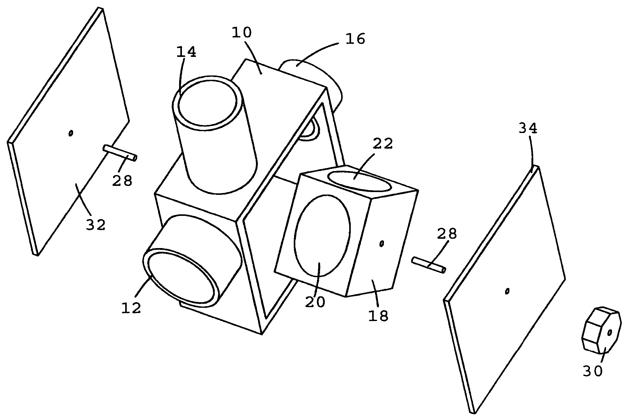
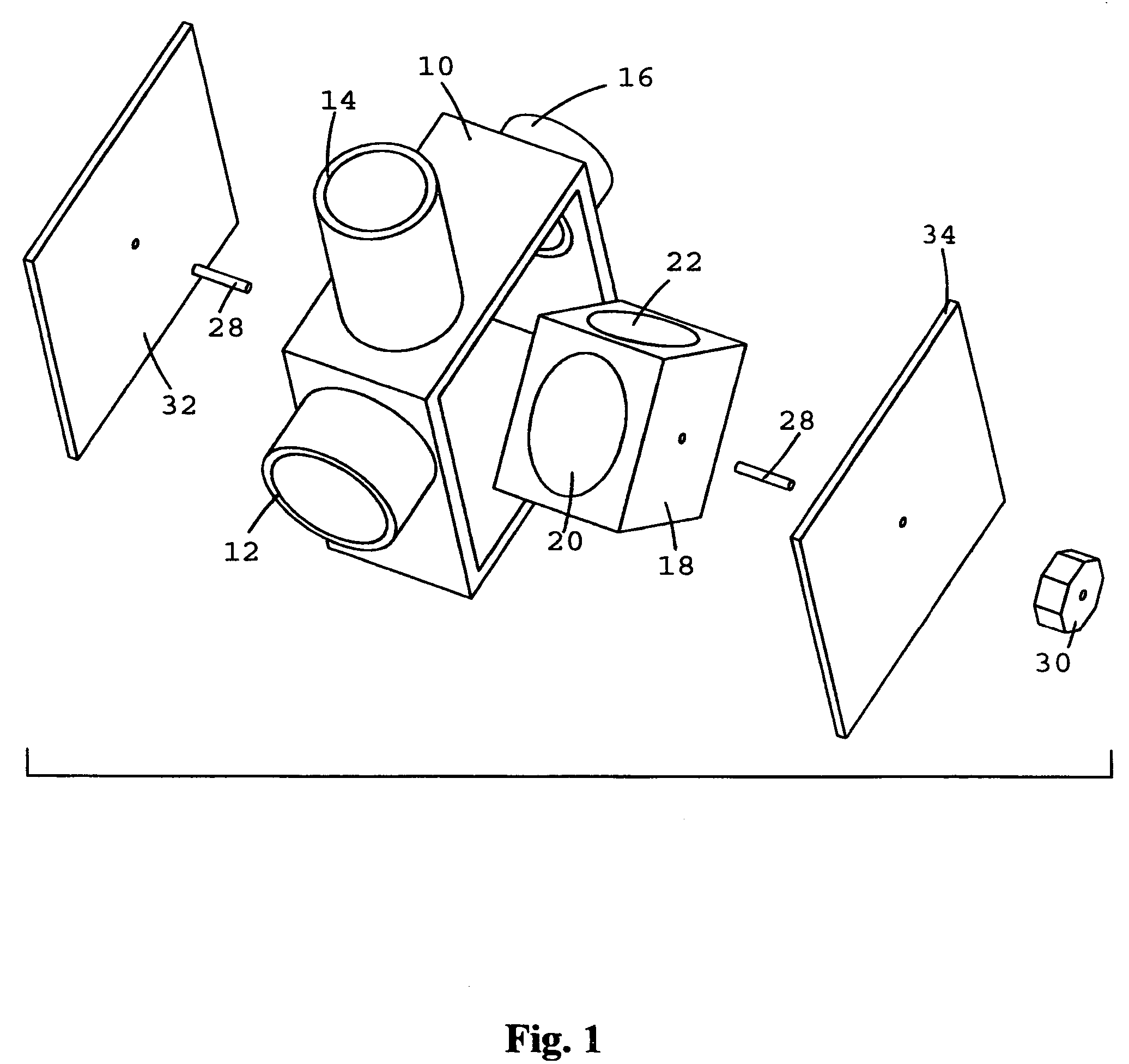
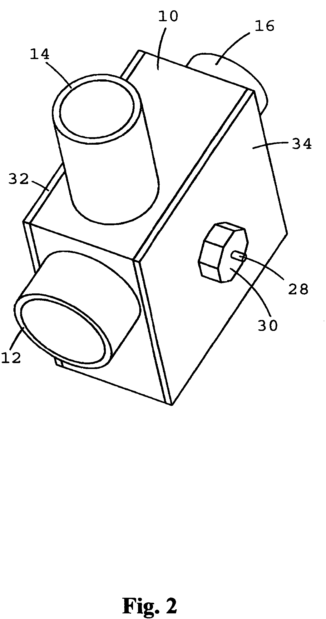
[0055]FIG. 1 is an exploded perspective view of an exemplary embodiment of the present invention. FIG. 2 is a perspective view of an exemplary embodiment of the present invention. As shown in FIGS. 1 and 2, the combined optical filter wheel, beamsplitter, switch, and logic gate is composed of a main housing 10, a primary tube 12, a secondary tube 14, a tertiary tube 16, and an optical routing subassembly 18. Said optical routing subassembly 18 is composed of a sub-housing constructed to hold filters and mirrors including a red interference filter 20, a green interference filter 22, a blue interference filter 24, a full reflective mirror 26, and an axle 28. Attached to axle 28 is a rotator 30 to facilitate rotation of optical routing subassembly 18. Optical routing subassembly 18 can be rotated to four different positions. Each rotational position of optical routing subassembly 18 places a different optic into the light path such that the angle of incidence of the light to the optics...


PUM


Abstract

A machine that can pass, reflect, filter, or block light along multiple paths. The specific portions of light that can be passed, reflected, blocked, or filtered, are controlled by an optical routing subassembly. This optical routing subassembly can be manipulated to direct specific portions of light to specific paths.

Description

RELATED APPLICATIONS [0001]The present application is a continuation application of U.S. provisional patent application, Ser. No. 60 / 577,524, filed Jun. 7, 2004, included by reference herein and for which benefit of the priority date is hereby claimed.FIELD OF THE INVENTION[0002]The present invention relates to optics, optical systems, telecommunications, photonics, and computation.BACKGROUND OF THE INVENTION[0003]There is a need for mechanisms that provide for high resolution imaging and tracking. There is also a need for mechanisms that provide for optical routing and switching. Additionally, there is a need for mechanisms that facilitate optical computation.Relevant prior art includes:[0004]U.S. Pat. No. 3861788January, 1975Webster359 / 889U.S. Pat. No. 4084909April, 1978Mathisen356 / 332U.S. Pat. No. 4176916December, 1979Carpenter359 / 589U.S. Pat. No. 4448500May, 1984Marling359 / 503U.S. Pat. No. 4738535April, 1988Webster356 / 418U.S. Pat. No. 4930883June, 1990Salzman359 / 419U.S. Pat. No....

Claims


Application Information

Patent Timeline
Patent Type & Authority Patents(United States)
IPC IPC(8): G02B6/00G02B21/36G02B26/02G02B6/34G02B6/35G02B7/00
CPCG02B26/007G02B6/29361G02B6/3512
Inventor THIBAULT, ANDRE SEAN
Owner KEYSTREAM LABS LLC
Learn More