
Installed instrumentation maintenance method

a technology for installing instruments and maintenance methods, applied in the field of devices, to achieve the effect of uniformly reducing calibration and maintenance requirements and reducing expenses

Inactive Publication Date: 2007-10-09
MCDONNELL THOMAS
View PDF13 Cites 6 Cited by
  • Summary
  • Abstract
  • Description
  • Claims
  • Application Information

AI Technical Summary

Benefits of technology

[0010]The present invention's methodology for evaluating maintenance requirements is founded on reliability-centered maintenance (RCM) principles. The inventors style the decision logic tree that typifies their invention an “Installed Instrumentation Maintenance Requirements and Maintenance Actions Logic” (I2MRMAL) Tree.” According to frequent inventive practice, the inventive I2MRMAL Tree is accompanied by a questionnaire referred to by the inventors as the “Installed Instrumentation (INST2) Questions.” The inventive INST2 Questions serve as a useful vehicle for facilitating practice of the inventive I2MRMAL Tree. The I2MRMAL Tree represents the present invention's logic; the INST2 Questions represent a tool for advancing the inventive process.
[0011]The inventive method represents an assessment mechanism that is uncomplicatedly practicable, yet complexly useful. Among the many possible applications, the present invention's assessment methodology can be used to perform engineering analysis on shipboard instrumentation in order to uniformly reduce calibration and maintenance requirements. For instance, by furthering reliability-centered maintenance goals, the present invention can potentially play an important role for the U.S. Navy in terms of providing decision-making models for maintenance of instrumentation operations. Inventive practice can thus significantly reduce the expenses (typically in millions of dollars) that the U.S. Navy incurs on instrumentation maintenance. It is noted in this regard that the present invention is the focal technical innovation of the 127-page Naval Sea Systems Command (NAVSEA) Shipboard Instrumentation and Systems Calibration (SISCAL) Transition Study Report, dated Jun. 2, 2003, incorporated herein by reference; see, e.g., the last paragraph of the Executive Summary.

Problems solved by technology

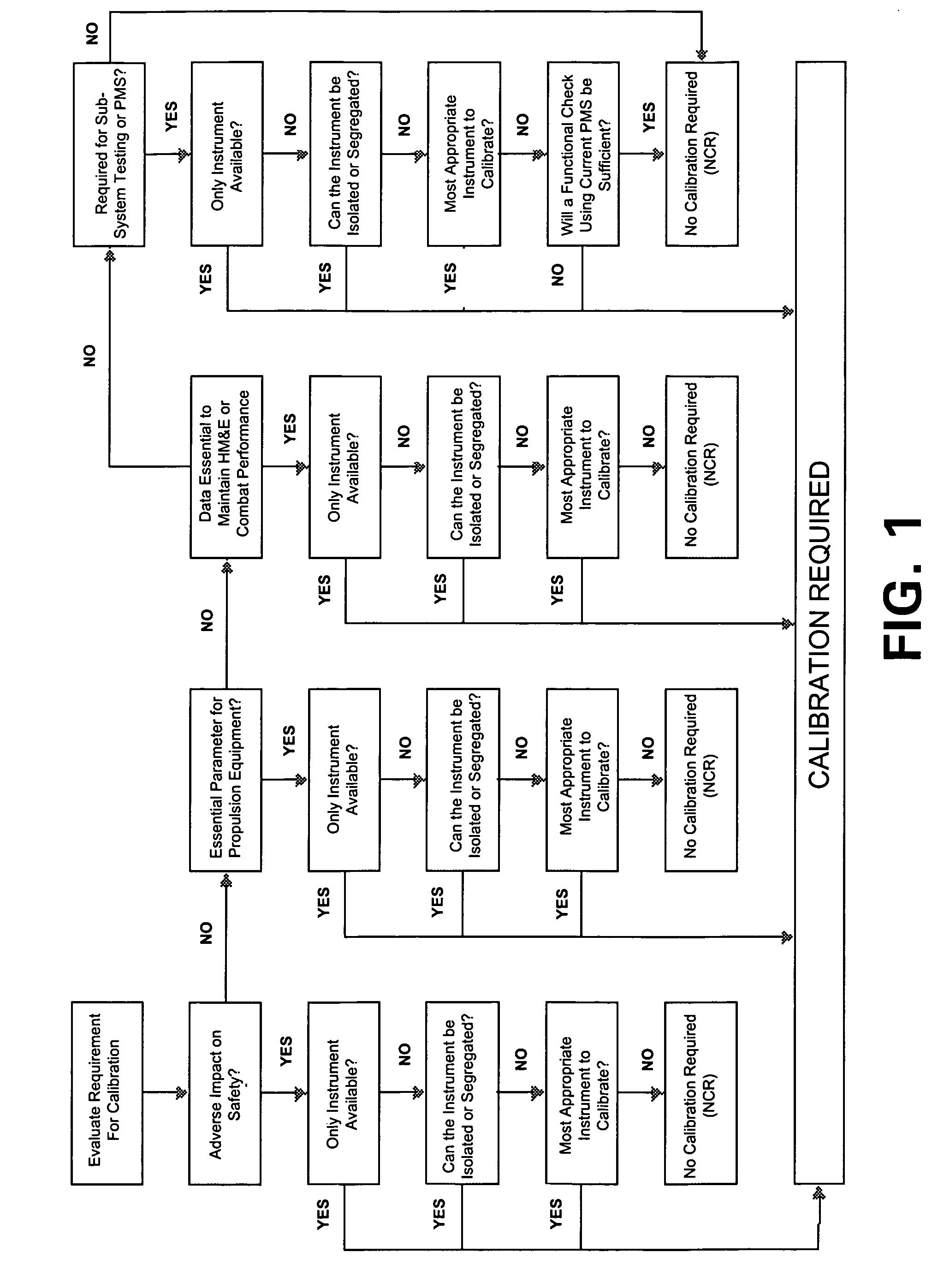
The JFFM's Calibration Decision Logic Tree does not reflect reliability-centered maintenance (RCM) principles; in particular, it neither addresses installed instrument applications, nor considers appropriate instrument tolerances, nor considers maintenance actions alternative to calibration.

Method used


Image

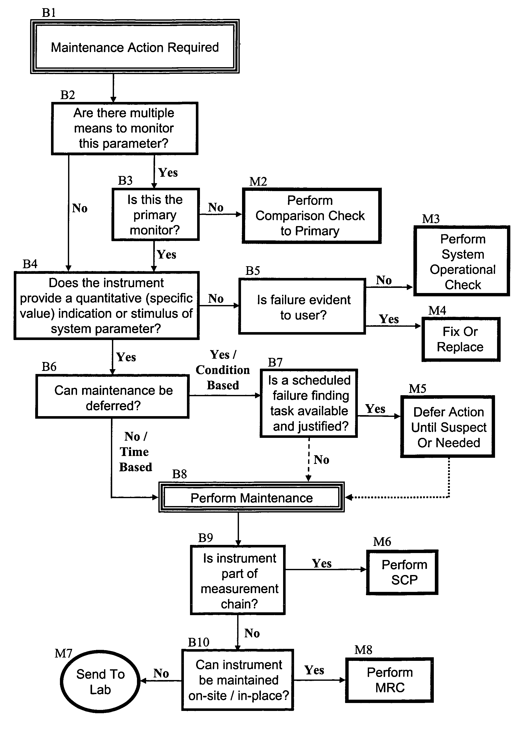
  • Installed instrumentation maintenance method
  • Installed instrumentation maintenance method
  • Installed instrumentation maintenance method

Examples


Embodiment Construction

[0020]Referring now to FIG. 1, the U.S. Navy currently implements an instrument maintenance strategy that separates calibration aspects from other maintenance-related aspects. The logic tree shown in FIG. 1 is the aforementioned duplicate of the “Calibration Decision Logic Tree” published in the Joint Fleet Maintenance Manual (JFFM, CINCLANTFLT / CINCPACFLTINST 4790.3) at Volume VI, Chapter 9, Appendix B-1. The U.S. Navy's currently conducts instrument calibration requirements analysis through its SISCAL Program, which uses a logic tree very similar to that shown in FIG. 1. As previously noted herein, the JFFM's Calibration Decision Logic Tree fails to effectuate reliability-centered maintenance (RCM) principles.

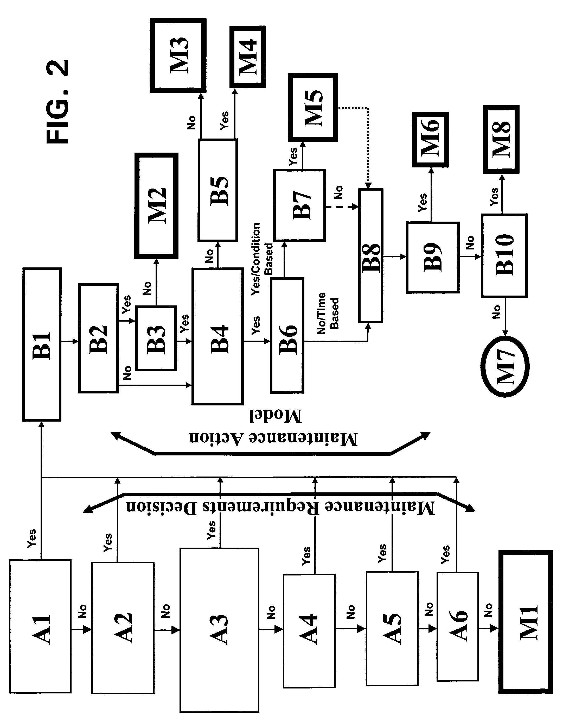
[0021]Reference is now made to FIG. 2 through FIG. 6, which are informative regarding the present invention. FIG. 2 through FIG. 4 illustrate the decision tree logic for a typical embodiment in accordance with the present invention. FIG. 2 is re-represented in two parts as FIG...


PUM


Abstract

The present invention's efficient and economical maintenance strategy for a system of operation (such as involving various kinds of instrumentation) features a unique decision-making logic that incorporates reliability-centered maintenance principles. The initial logical inquiry filters out the non-critical cases, i.e., those instruments the failure of which does not jeopardize or compromise safety, or the environment, or an important function or operation. The logical construct proceeds as to the remaining (unfiltered) instruments in a series of logical steps wherein the satisfaction of one or more given conditions by a subject instrument directs the practitioner to the appropriate maintenance action for the subject instrument. Possible maintenance actions include the following: comparison check of the instrument with respect to the primary instrument; system operational check; repair of the instrument; replacement of the instrument; maintenance deferral until a scheduled failure finding task; system calibration procedure; individual maintenance procedure (on-site or off-site).

Description

CROSS-REFERENCE TO RELATED APPLICATIONS[0001]This application claims the benefit of U.S. Provisional Application No. 60 / 558,899, filed 2 Apr. 2004, inventors Jeffrey T. Eker, Shawn A. Egnak, Charles L. Savage, Margaret A. Connolly and Vincent L. DiFilippo, invention entitled “Installed Instrumentation Maintenance Method,” incorporated herein by reference.STATEMENT OF GOVERNMENT INTEREST[0002]The invention described herein may be manufactured and used by or for the Government of the United States of America for governmental purposes without the payment of any royalties thereon or therefor.BACKGROUND OF THE INVENTION[0003]The present invention relates to devices that require periodic maintenance such as involving calibration, more particularly to methods for systematically applying maintenance procedures to groups of such devices.[0004]Four traditional maintenance strategies are “reactive” maintenance (also known as “run-to failure” maintenance), “preventive” maintenance (also known a...

Claims


Application Information

Patent Timeline
IPC IPC(8): G01B3/44G06F11/30
CPCG06Q10/06Y10S707/99948Y10S707/99945
Inventor EKER, JEFFREY T.EGNAK, SHAWN A.SAVAGE, CHARLES L.CONNOLLY, MARGARET A.DIFILIPPO, VINCENT L.
Owner MCDONNELL THOMAS
Learn More