

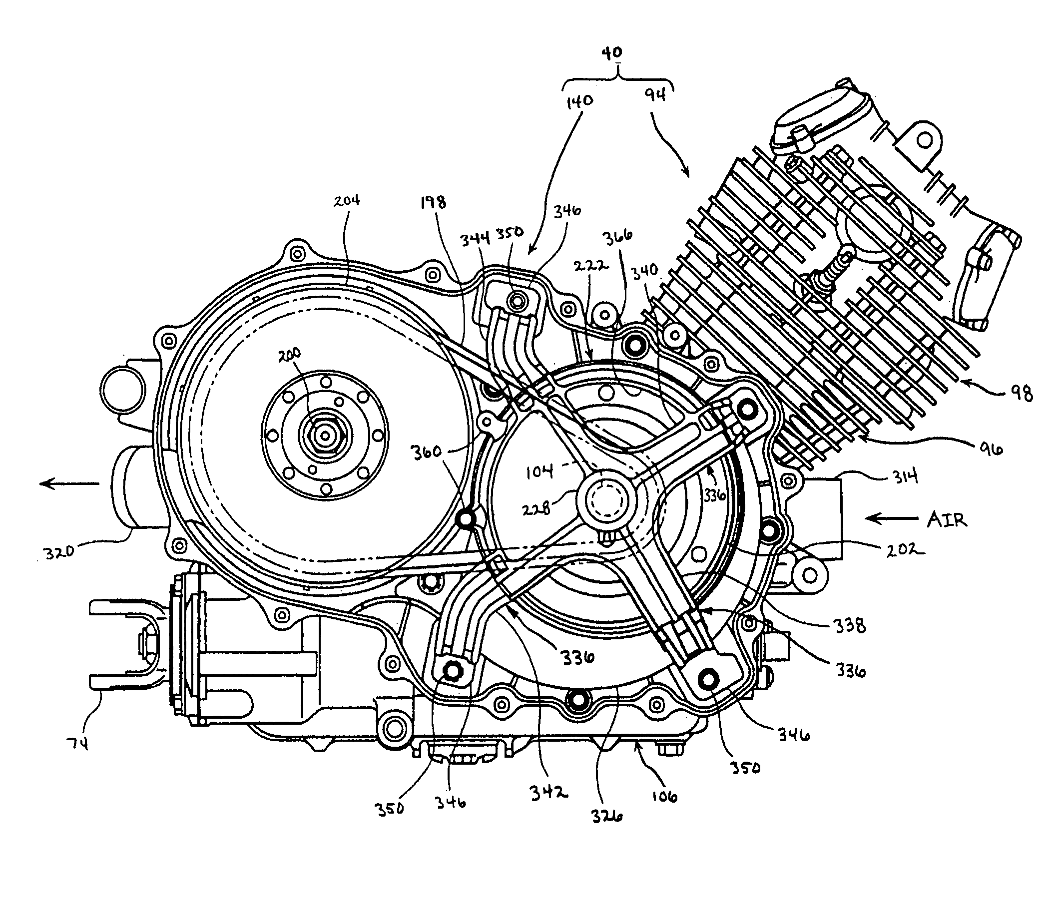
Drive belt cooling structure for engine
a cooling structure and driving belt technology, applied in the direction of guards, couplings, cycle equipment, etc., can solve the problems of reducing the useful life of shafts, reducing the useful life of various components of transmission, and requiring the transmission of crankshafts
- Summary
- Abstract
- Description
- Claims
- Application Information
AI Technical Summary
Benefits of technology
Problems solved by technology
Method used
Image

Examples
Embodiment Construction
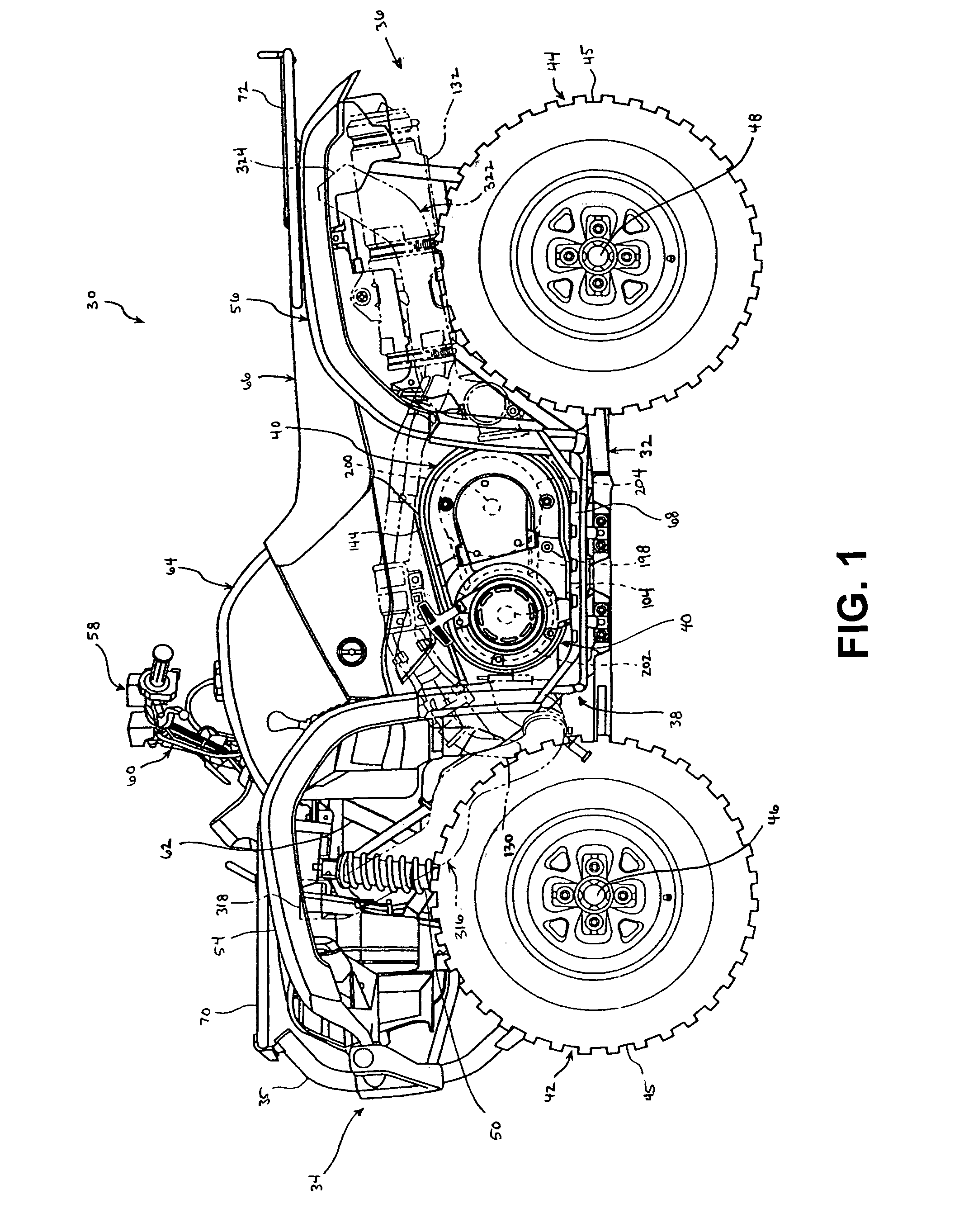
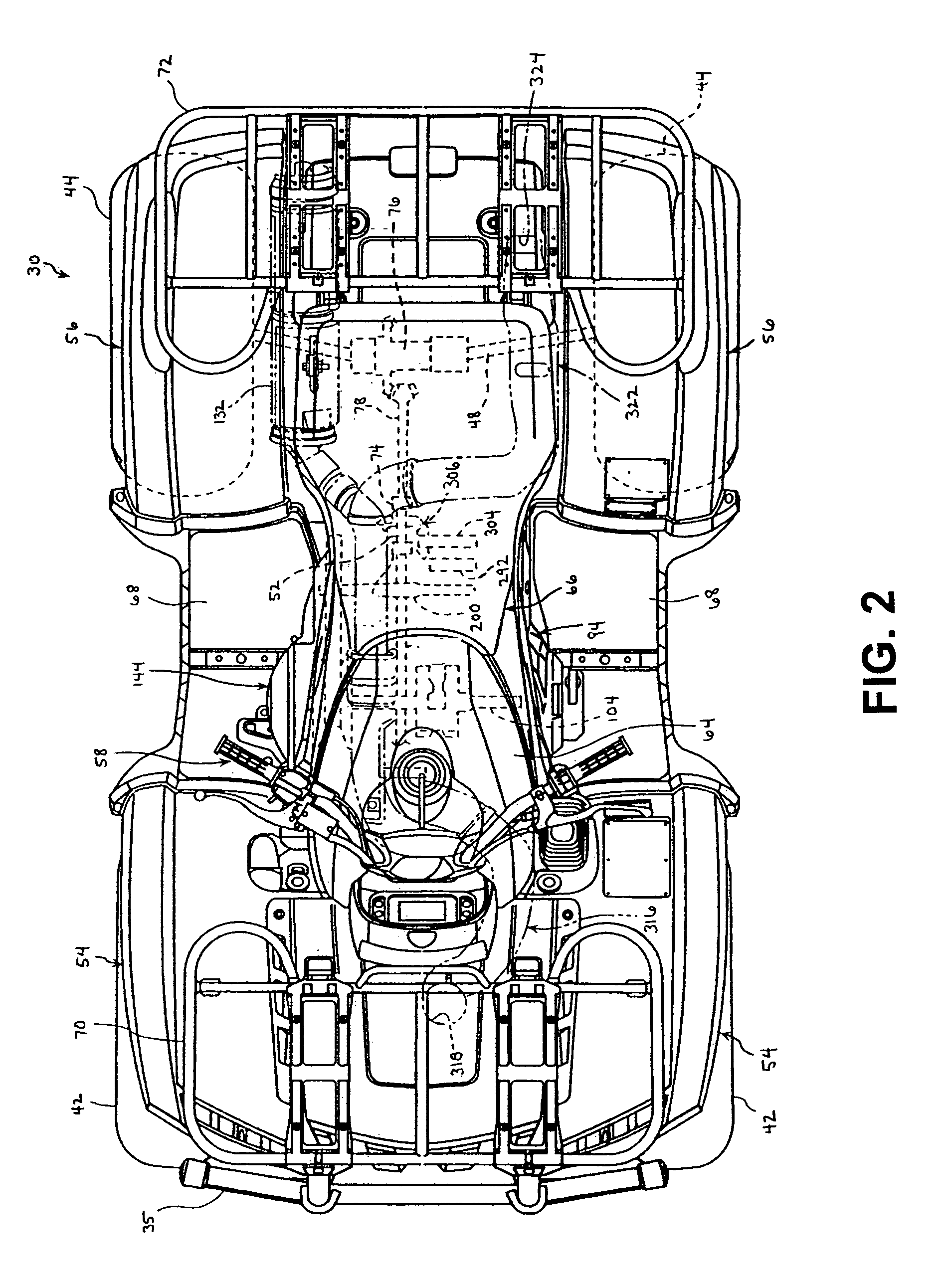
[0025]FIGS. 1-11 illustrate a preferred embodiment of an engine structure for an offroad vehicle. Referring to FIG. 1, the offroad vehicle comprises an all-terrain vehicle 30 or “ATV.” While the engine structure of the preferred embodiment is described with this particular type of vehicle 30, those of skill in the art will appreciate that the engine structure may have utility in a wide range of applications.
[0026]In FIG. 1, the all terrain vehicle 30 is shown in side view, the vehicle 30 having a frame 32. The frame 32 connects a front end 34 of the vehicle 30, the front end 34 having a front bumper 35, with a rear end 36 of the vehicle 30. An engine compartment 38 (i.e., a compartment in which the engine 40 is mounted) is defined by the frame 32, and an engine 40 is disposed within the engine compartment 38.
[0027]The frame 32 is rollably supported by a pair of front wheels 42 and a pair of rear wheels 44. The front and rear wheels 42, 44 having inflated tires 45. Each front wheel i...
PUM
 Abstract
Description
Claims
Application Information