Emission control apparatus

a technology of emission control and exhaust gas, which is applied in the direction of lighting and heating apparatus, machines/engines, and separation processes, etc., can solve the problems of increasing pressure drop, directing untreated exhaust gases to the atmosphere, and requiring frequent replacement of catalysts, so as to reduce noise and air pollution, improve the distribution of exhaust gas flow, and reduce noise.

Inactive Publication Date: 2007-10-16
CLEAN AIR POWER
View PDF6 Cites 23 Cited by
  • Summary
  • Abstract
  • Description
  • Claims
  • Application Information

AI Technical Summary

Benefits of technology

[0018]The present invention provides apparatus for controlling emissions from an internal combustion engine to reduce noxious gas emissions and to reduce noise therefrom. The apparatus may include an enclosed housing having an inlet at one end thereof for connection with the exhaust of an internal combustion engine and an outlet through which the exhaust gases may be discharged to the atmosphere. Both noise reduction means and noxious gas converter means may be disposed in the housing.
[0019]The converter means, coaxially mounted in the housing, is characterized by a catalytic module the center which is formed around a tubular member providing a honeycomb type catalytic cell of annular cross section the inner diameter of which is substantially the same as the outer diameter of the tubular member and the outer diameter of which is somewhat less than the inner diameter of the housing. Exhaust gases from the engine flow from the housing inlet through the tubular member into an expansion chamber then through the catalytic cell, where the nitrogen oxides, carbon monoxides and unburned carbons thereof are converted to less noxious compounds, and into at least one other expansion chamber before being discharged through the outlet. By preventing concentrated flow through the center of the catalytic cell and by redirecting flow from the expansion chamber through the larger diameter catalytic cell of annular cross section, exhaust gases through the catalytic cell are more evenly distributed and the velocity thereof is reduced, increasing the residence time and efficiency of conversion in the catalytic cell.
[0020]In preferred embodiments of the invention, the housing is divided by partitions into four chambers: a first chamber nearest the inlet, a second converter chamber in which the annular catalytic cell is disposed, a third chamber next to said converter chamber, and a fourth outlet chamber. A coaxial tubular member provides for flow of exhaust gases from the inlet into the third chamber where it expands, then through the converter chamber and into the first chamber, another expansion chamber. Additional tubular members provide for flow to the fourth chamber prior to discharge through the outlet. Tubular members of various sizes and dispositions may be provided with perforation to reduce pulsation and noise emitted from the engine exhaust. The catalytic module, being surrounded by and in contact with hot exhaust cases is subject to faster heating and hence reaches conversion efficiency at a faster rate.
[0022]Thus, the present invention provides for reduction of noxious gases and, in preferred embodiments, reduction of noise, in a unique combination especially characterized by better distribution of exhaust gas flow through the catalytic converter portion thereof. The combination provided by the emission control apparatus of the present invention is one which takes advantages of chemical, dynamic fluid flow and acoustic principles in a combination which results in superior reduction of noise and air pollution.
[0023]A primary feature of the present invention is the utilization of volume within the silencer to reduce velocity of the exhaust gasses and to provide best flow distribution at the catalyst face. The reduction of exhaust gas velocity at the catalyst face and the equal distribution of exhaust gasses across the catalyst face greatly reduces, if not completely eliminates, the concentration of high velocity at the catalyst face. The design also provides the ability to penetrate the catalyst substrate without fear of damage to catalyst surfaces. Penetration of the catalyst substrate allows a great deal of design flexibility to configure the converter / silencer to meet space limitation and to facilitate ease of manufacture. Many other objects and advantages of the invention will be apparent from the description which follows in conjunction with the accompanying drawings.

Problems solved by technology

Such designs resulted in increased pressure drop, required frequent replacement of catalyst and required inspiration of atmospheric air to aid in oxidation of carbon monoxide and unburned hydrocarbons.
This would result in directing untreated, polluted exhaust gases to the atmosphere.
Problems associated with three-way catalytic converters have been identified as: imprecise air / fuel ratio control, deactivation of the catalyst and flow maldistribution at the front area of the catalytic converter.
As previously stated, one of the primary problems to consider in a combined catalytic converter and exhaust silencer, particularly for efficiency of catalytic conversion, is flow distribution.
Other results of research show that when a truncated conical inlet transition is provided exhaust gases recirculate around the transition causing flow maldistribution and scattered hot and cold spots in the frontal area of the catalyst module, reducing conversion efficiency.
This creates higher back pressures, raising the mean effective pressure in the exhaust system between the catalytic converter and the engine exhaust valves.
Undersized exhaust silencers can also increase the back pressure and when coupled with an undersized catalytic converter multiply the back pressure many times over, reducing operational efficiency of the engine.

Method used


Image

  • Emission control apparatus
  • Emission control apparatus

Examples


Embodiment Construction

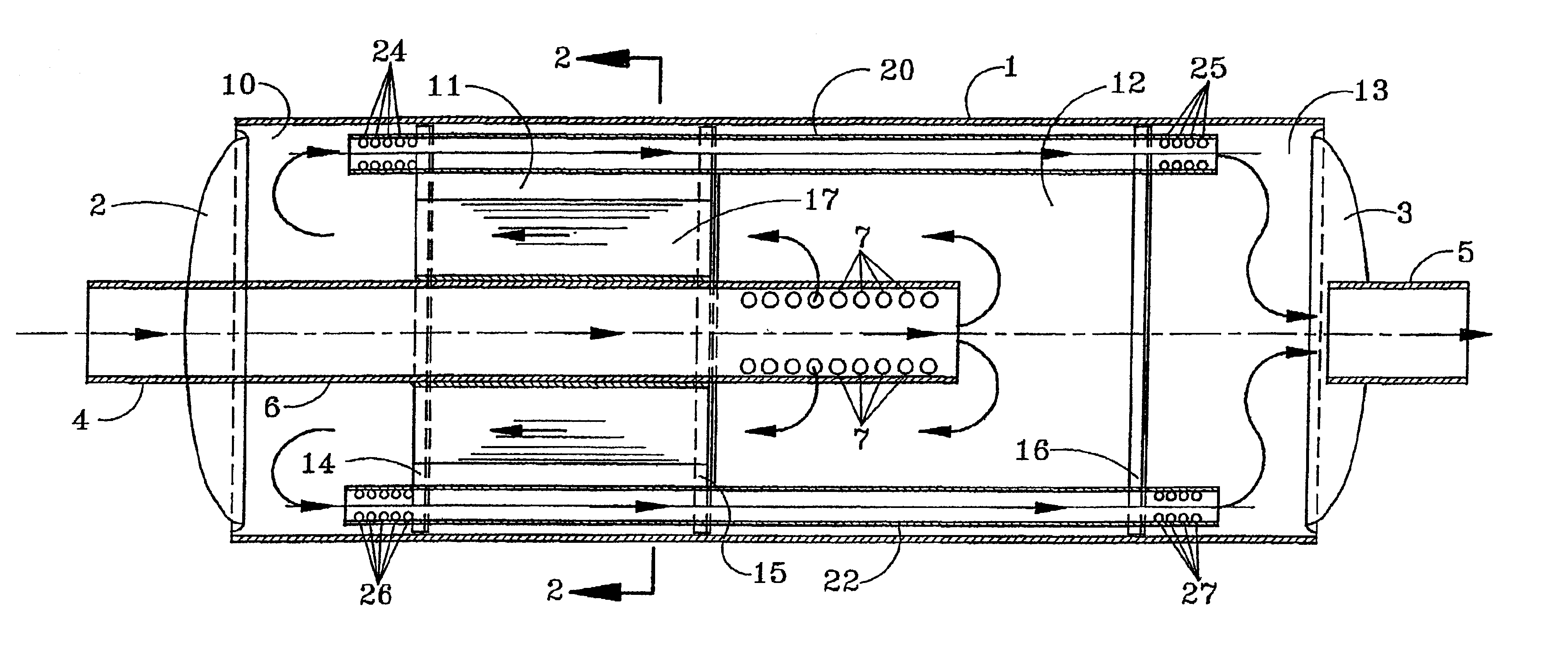
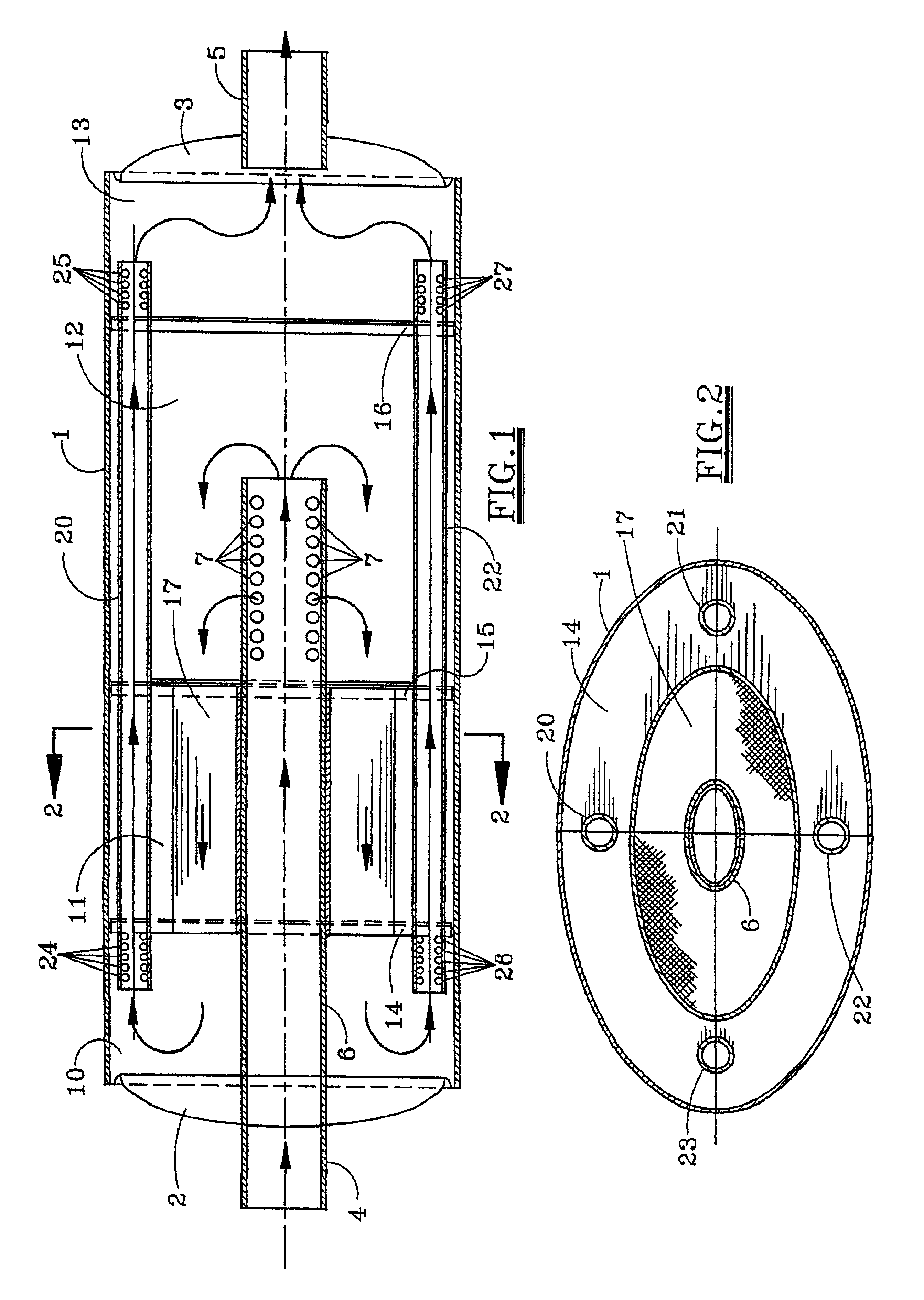
[0026]Referring first to FIGS. 1 and 2, there is shown an apparatus for controlling emissions from an internal combustion engine. The apparatus is a combination noise and pollution control apparatus, particularly adapted for use with an automobile. It includes a cylindrical housing 1 closed at opposite ends by dished heads 2 and 3. The housing 1 can be cylindrical or, as in the preferred embodiment illustrated in FIGS. 1 and 2, of elliptical cross-section. If cylindrical, the heads 2 and 3 are semi-spherical. If elliptical, they are semi-elliptical in shape. The head 2 is provided with a single inlet 4 by which the apparatus may be connected to the exhaust (not shown) of an internal combustion engine (not shown). The opposite head 3 is provided with an outlet 5. The outlet 5 may be connected to a discharge pipe (not shown) or in the case of an automobile to the tailpipe (not shown). In the exemplary embodiment, the inlet 4 is formed by the end of a tubular member 6 which is coaxiall...


PUM

PropertyMeasurementUnit
diameteraaaaaaaaaa
pressure dropaaaaaaaaaa
pressureaaaaaaaaaa

Abstract

Apparatus for controlling emissions from an internal combustion engine including an enclosed housing one end of which is provided with an inlet and the other end an outlet. A coaxial tubular member extends from the inlet into the housing. A catalytic cell surrounds the tubular member and separates two chambers, a first surrounding the tubular member near the inlet and the other on the opposite side of the catalytic cell. Exhaust gases from the internal combustion engine flow through the tubular member, expanding into the other chamber, then through the catalytic cell for conversion of nitrogen oxides, carbon monoxide and unburned hydrocarbons to less noxious components, expanding into the first chamber for eventual discharge through the outlet.

Description

CROSS-REFERENCE TO RELATED APPLICATION[0001]The present application is a continuation-in-part of application Ser. No. 09 / 228,479 filed Jan. 11, 1999, now abandoned.BACKGROUND OF THE INVENTION[0002]1. Field of the Invention[0003]The present invention pertains to apparatus for use with internal combustion engines to reduce emission of noxious gases and noise emitted therefrom. More specifically, the present invention pertains to apparatus, particularly suited for use with spark ignited, four cycle, carbureted or injected engines, for converting nitrogen oxides, carbon monoxides and unburned hydrocarbons from the exhaust of such engines to less noxious compounds and for reducing the noise emitted therefrom.[0004]2. Brief Description of the Prior Art[0005]Both noise and air pollution have been of increasing concern in recent years. Silencers or mufflers for noise reduction of internal combustion engines have existed for many years. Most silencers utilize some type of housing in which is...

Claims


Application Information

Patent Timeline
Patent Type & Authority Patents(United States)
IPC IPC(8): B01D53/34F01N3/28B01D53/94F01N1/08
CPCB01D53/9454F01N1/084F01N3/2885Y02T10/22F01N2470/10Y02T10/12
Inventor HARRIS, HAROLD L.
Owner CLEAN AIR POWER
Why Eureka
Try Eureka