
Manual switch remote controller

a remote controller and switch technology, applied in the direction of relays, point operation from vehicles, transportation and packaging, etc., can solve the problems of costly labor loss, loss of time, and failure of switch machines to operate properly in the railroad industry

Inactive Publication Date: 2007-10-16
RIDGEWAY CHARLES S
View PDF4 Cites 9 Cited by
  • Summary
  • Abstract
  • Description
  • Claims
  • Application Information

AI Technical Summary

Benefits of technology

Prevents back and shoulder injuries by enabling remote electrical control of switch points, reducing labor costs and time losses associated with manual cranking, while maintaining compatibility with existing power switch machines.

Problems solved by technology

Unfortunately, at times these power switch machines fail to operate properly and Railroad Signal Maintenance Personnel are needed to be sent to the remote locations or sites where the machines have been installed in order to make repairs and / or perform tests.
Since some of the switch points consist of a section of rail which is up to thirty-nine (39) feet in length and weigh a little more than 45 lbs / ft, this manual cranking has frequently lead to back and shoulder injuries to the user which has resulted in costly labor loss and loss of time within the Railroad Industry.

Method used


Image

  • Manual switch remote controller
  • Manual switch remote controller
  • Manual switch remote controller

Examples


Embodiment Construction

[0022]It is to be distinctly understood at the outset that the present invention shown in the drawings and described in detail in conjunction with the preferred embodiments is not intended to serve as a limitation upon the scope or teachings thereof, but is to be considered merely as an exemplification of the principles of the present invention.

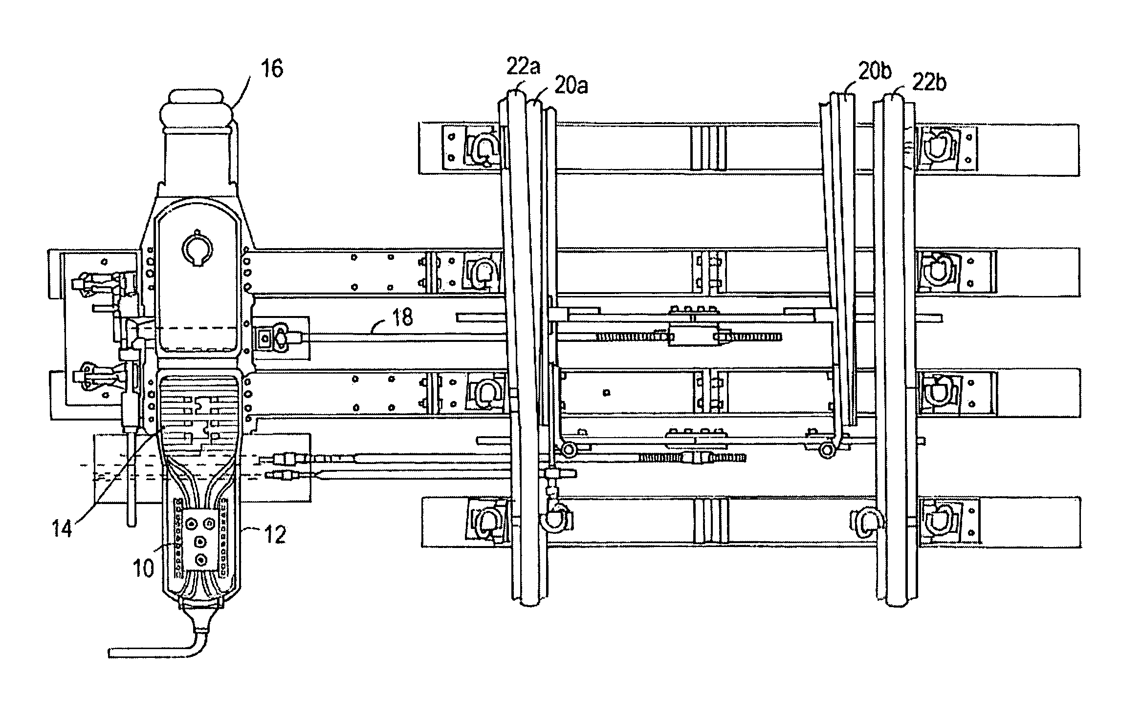
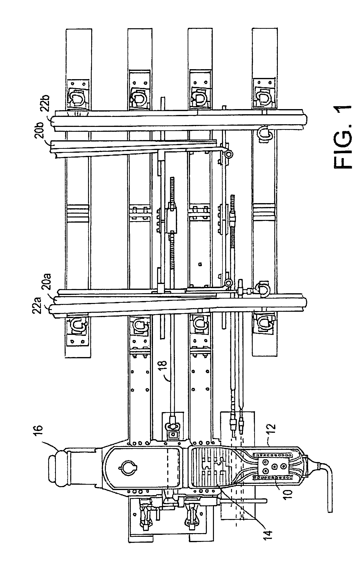
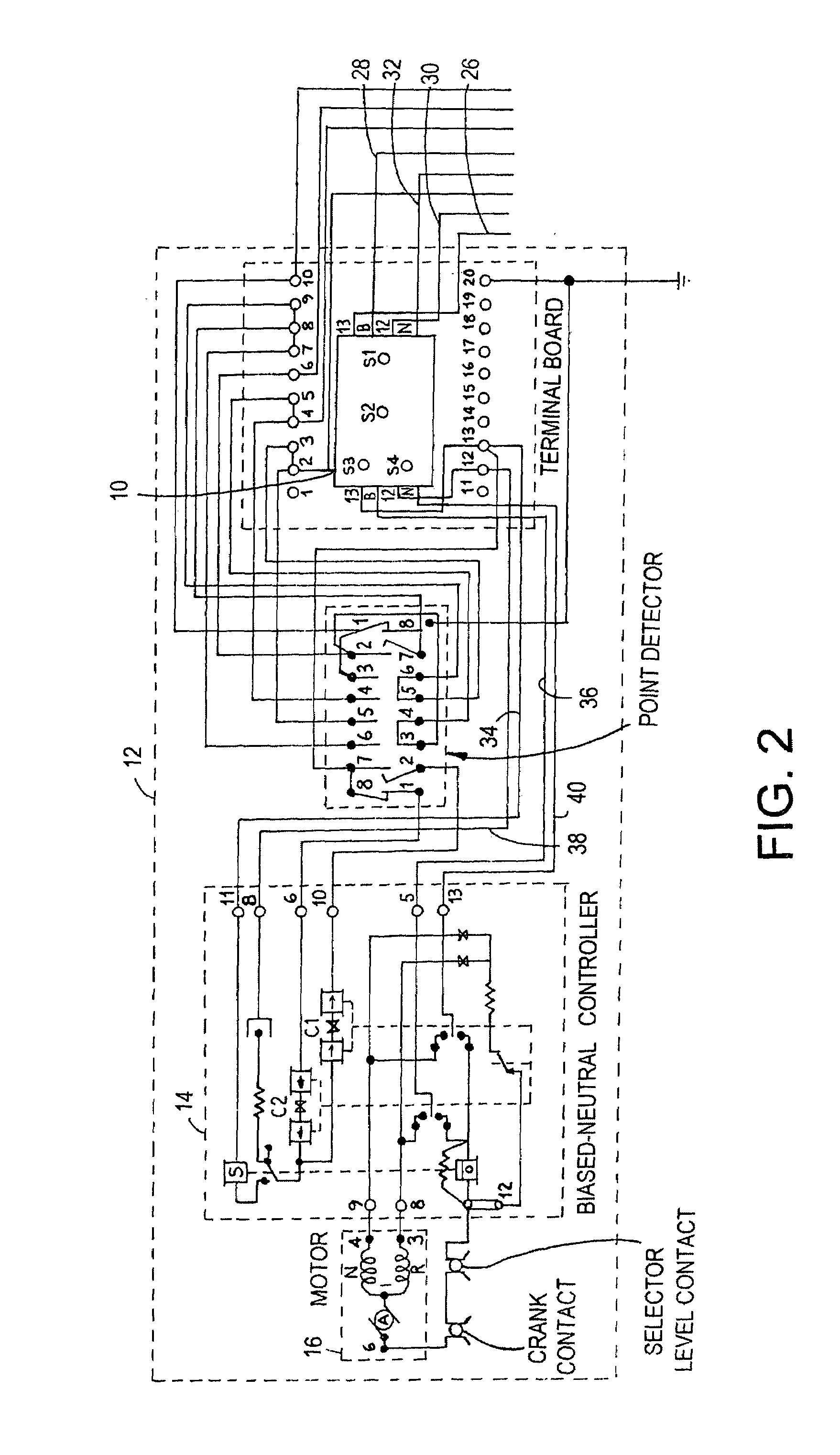
[0023]Referring now in detail to the drawings, there is illustrated in FIG. 1 a top plan view of a manual switch remote controller 10, constructed in accordance with the principles of the present invention, which has been installed as an add-on feature into controlling circuits of an existing a power switch machine 12. The present manual switch remote controller 10 is especially designed for suitable use with a power switch machine similar to the type which is manufactured and sold by Alstom Signaling Inc. of Rochester, N.Y., as their Models 5H, 5G and 5D.

[0024]For example, the controller 10 can also be used with other power switch machines w...


PUM


Abstract

A manual switch remote controller is adapted for use with a power switch machine to electrically and selectively move switch points of a track switch between a normal position and a reverse position from a remote location in the field. In one preferred embodiment, the manual switch remote controller includes a first switch for selectively connecting and disconnecting a first source of DC operating power from first and second input terminals to first and second output terminals which are coupled to respective first and second input operating terminals of a biased-neutral controller. A second switch is used for selectively connecting and disconnecting a second source of DC controlling power from third and fourth input terminals to third and fourth output terminals which are coupled to respective third and fourth input control terminals of the biased-neutral controller. Third and fourth switches are used for selectively connecting the first source of DC operating power from the first and second input terminal, when momentarily actuated, to the third and fourth output terminals with first and second polarities so as to cause the biased-neutral controller to energize either the reverse or normal field winding of the DC motor in order to electrically and selectively move the switch points between the normal and reverse positions.

Description

BACKGROUND OF THE INVENTION[0001]1. Field of the Invention[0002]This invention relates generally to railway track switch control apparatus and more particularly, the present invention relates to a manual switch remote controller adapted for use with a power switch machine to electrically move switch points of a track switch between a first position and a second position from a remote location in the field.[0003]2. Description of the Prior Art[0004]As is generally known in the Railroad Industry, power (electric) switch machines are used for operating a throw bar so as to move the switch points of a track switch or “throw the switch” into either a normal position or a reverse position. Normally, the power switch machines are controlled and operated by a train dispatcher or control operator sitting at a control office having a control panel. The control office is generally located at a great distance from the remote locations of the power switch machines.[0005]In order to permit moveme...

Claims


Application Information

Patent Timeline
Patent Type & Authority Patents(United States)
IPC IPC(8): B61L5/00B61L11/08H01H19/14H02B1/24B61L5/06
CPCB61L5/06
Inventor RIDGEWAY, CHARLES S.
Owner RIDGEWAY CHARLES S
Learn More