System for driving brushless DC motor and method of driving same

a brushless dc motor and drive system technology, applied in the direction of motor/generator/converter stopper, electronic commutator, dynamo-electric converter control, etc., can solve the problems of poor efficiency large vibration, and achieve the effect of high efficiency and small vibration of brushless dc motor

Active Publication Date: 2007-10-16
JAPAN SERVO CO LTD
View PDF3 Cites 2 Cited by
  • Summary
  • Abstract
  • Description
  • Claims
  • Application Information

AI Technical Summary

Benefits of technology

[0007]It is therefore an object of the invention to provide a brushless DC motor drive system capable of driving a brushless DC motor with high efficiency and small vibration, in all speed regions, and a method of driving the brushless DC motor.
[0010]With the brushless DC motor drive system and the method of driving the brushless DC motor, respective energization signals are always turned ON in regions where the absolute value of the induced voltage is large even if a speed command value varies, and a winding current flows to the respective stator windings when the absolute value of the induced voltage becomes large, so that the brushless DC motor can be driven with high efficiency in all speed regions, and vibration of the brushless DC motor becomes smaller.

Problems solved by technology

With the brushless DC motor drive system as described, however, the same has drawbacks in that because the energization signal is turned ON in a region where the induced voltage drops, the brushless DC motor is poor in efficiency and further, its vibration is large.

Method used


Image

  • System for driving brushless DC motor and method of driving same
  • System for driving brushless DC motor and method of driving same
  • System for driving brushless DC motor and method of driving same

Examples


Embodiment Construction

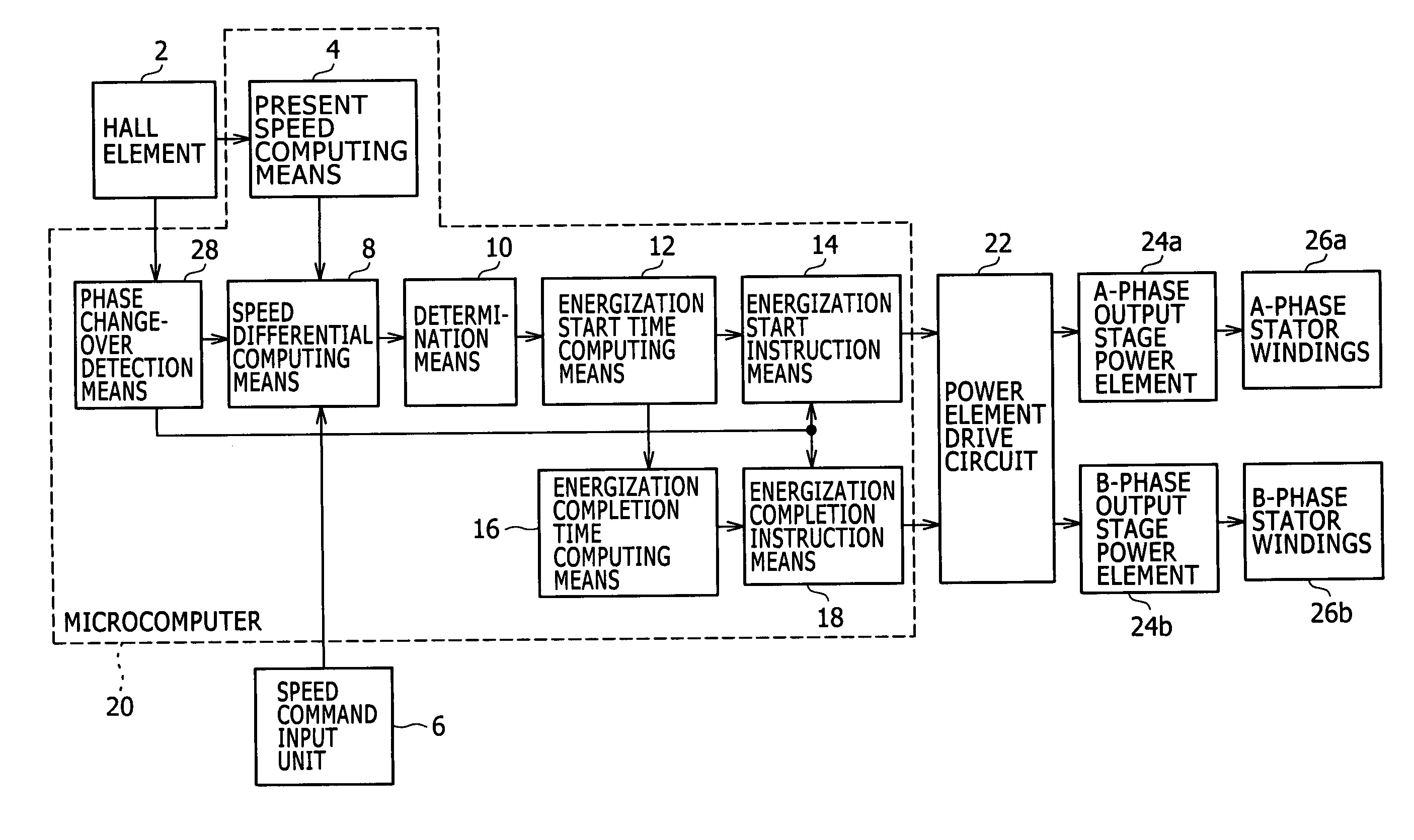
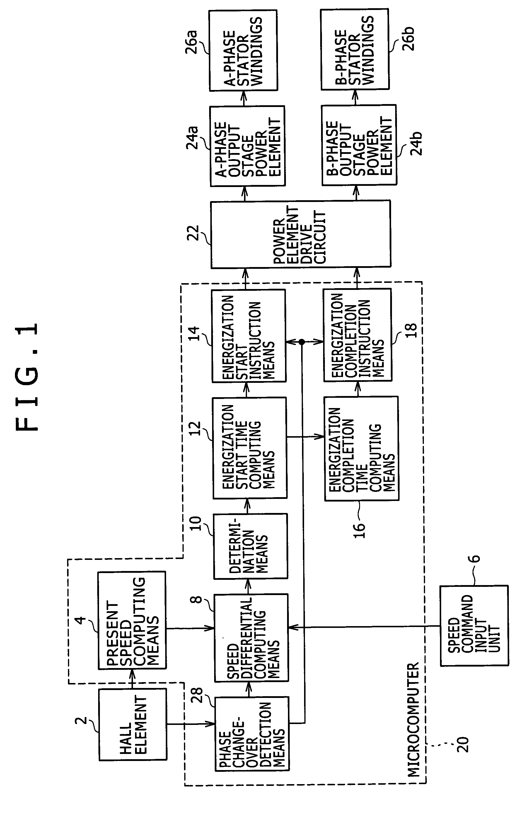
[0015]An embodiment of a brushless DC motor drive system according to the invention is described hereinafter with reference to FIG. 1. There are provided a Hall element 2 for detecting respective pole positions of permanent magnets of a rotor of a brushless DC motor, a present speed computing means 4 for computing a present speed of the brushless DC motor on the basis of an output signal from the Hall element 2, a speed command input unit 6 for inputting a speed command, a phase changeover detection means 28 for detecting a phase changeover on the basis of the output signal from the Hall element 2, a speed differential computing means 8 for computing a difference between the speed command and the present speed, that is, a speed differential Δv when the phase changeover is detected by the phase changeover detection means 28, a determination means 10 for determining whether the speed differential Δv is positive, zero or negative, an energization start time computing means 12 for compu...


PUM


Abstract

A brushless DC motor drive system includes a pole-position detector for detecting respective pole positions of permanent magnets of a rotor of a brushless DC motor. A present speed computing unit computes a present speed of the brushless DC motor on the basis of an output signal from the pole-position detector. A speed differential computing unit computes a speed differential between a speed command and the present speed. An energization start time computing unit computes an energization start time in a present instance on the basis of an energization start time in a preceding instance, and the speed differential. An energization start instruction unit instructs energization start upon the elapse of the energization start time in the present instance from a phase changeover point in time. An energization completion time computing unit computes an energization completion time by subtracting the energization start time in the present instance from preceding pulse time. An energization completion instruction unit instructs energization completion upon the elapse of the energization completion time from the phase changeover point in time.

Description

BACKGROUND OF THE INVENTION[0001]1. Field of the Invention[0002]The invention relates to a brushless DC motor drive system for driving a fan, blower and so forth, and a method of driving the brushless DC motor.[0003]2. Description of the Related Art[0004]With a brushless DC motor for driving a fan and blower, there has lately been an increase in demand for high power and variable speed, and a variable speed range is required to have a wide scope ranging from high-speed to low-speed.[0005]With the conventional brushless DC motor drive system, for controlling a duty angle, a rotational speed of a brushless DC motor is varied by adjusting a time length from a point in time when an induced voltage is turned from zero up to a point in time when an energization signal is turned ON, and by turning the energization signal OFF when the induced voltage is turned to zero again.[0006]With the brushless DC motor drive system as described, however, the same has drawbacks in that because the energ...

Claims


Application Information

Patent Timeline
Patent Type & Authority Patents(United States)
IPC IPC(8): H02K21/00
CPCH02P6/165H02P6/10H02P6/17Y02P80/10
Inventor MATSUHASHI, SYUICHI
Owner JAPAN SERVO CO LTD
Why Eureka
Try Eureka