Supercharge Your Innovation With Domain-Expert AI Agents!

Axial leaded over-current protection device

a protection device and axial leaded technology, applied in the direction of resistor details, resistor mounting/supporting, positive temperature coefficient thermistors, etc., can solve the problems of over-current protection device tripping, tremendous limitation etc., to reduce the resistance of over-current protection devices and the volume of over-current protection

Active Publication Date: 2007-10-16
POLYTRONICS TECH
View PDF9 Cites 5 Cited by
  • Summary
  • Abstract
  • Description
  • Claims
  • Application Information

AI Technical Summary

Benefits of technology

The present invention provides an axial leaded over-current protection device with low resistance to expand its applications. The device includes multiple PTC devices, a first terminal metal strip, and a second terminal metal strip. The PTC devices are connected in parallel through the first and second terminal metal strips, which reduces the resistance of the device. This allows for its use in small appliances without significantly increasing its volume.

Problems solved by technology

However, because the process temperature of injection molding is relatively high, the over-current protection device on the battery would be tripped.
If the recovery of the over-current protection device is worse after being tripped, the applications of the over-current protection device are tremendously limited due to its high initial resistance.

Method used


Image

  • Axial leaded over-current protection device
  • Axial leaded over-current protection device
  • Axial leaded over-current protection device

Examples


Embodiment Construction

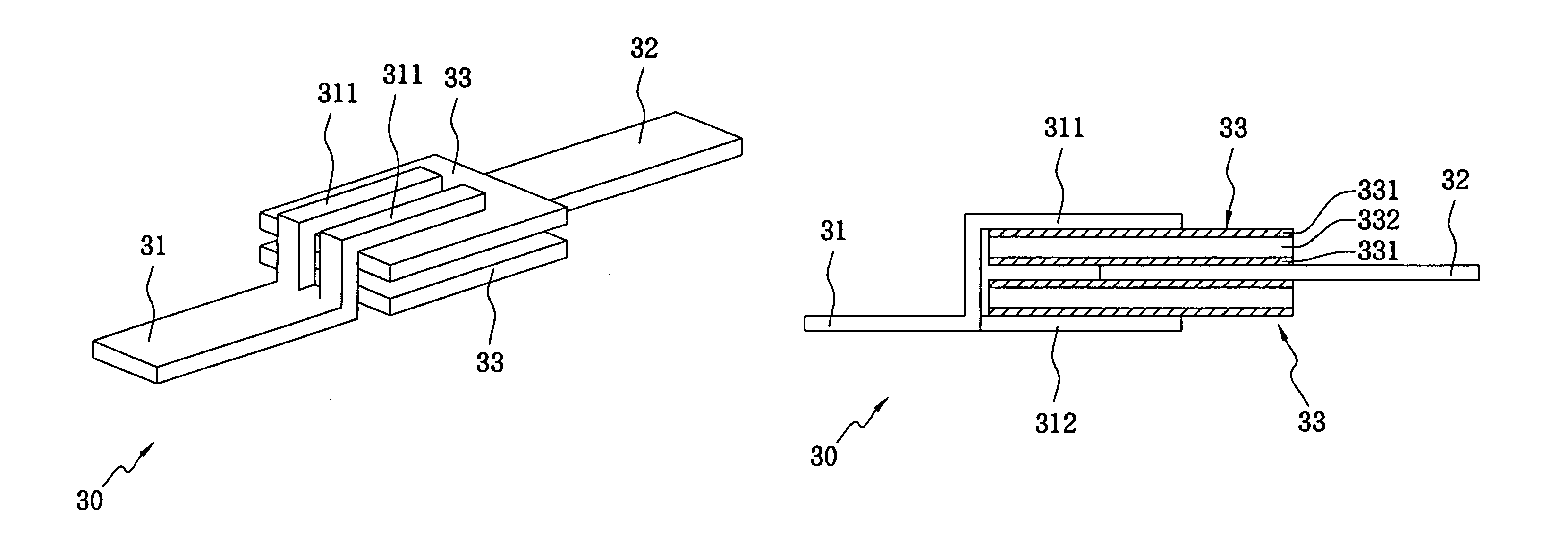
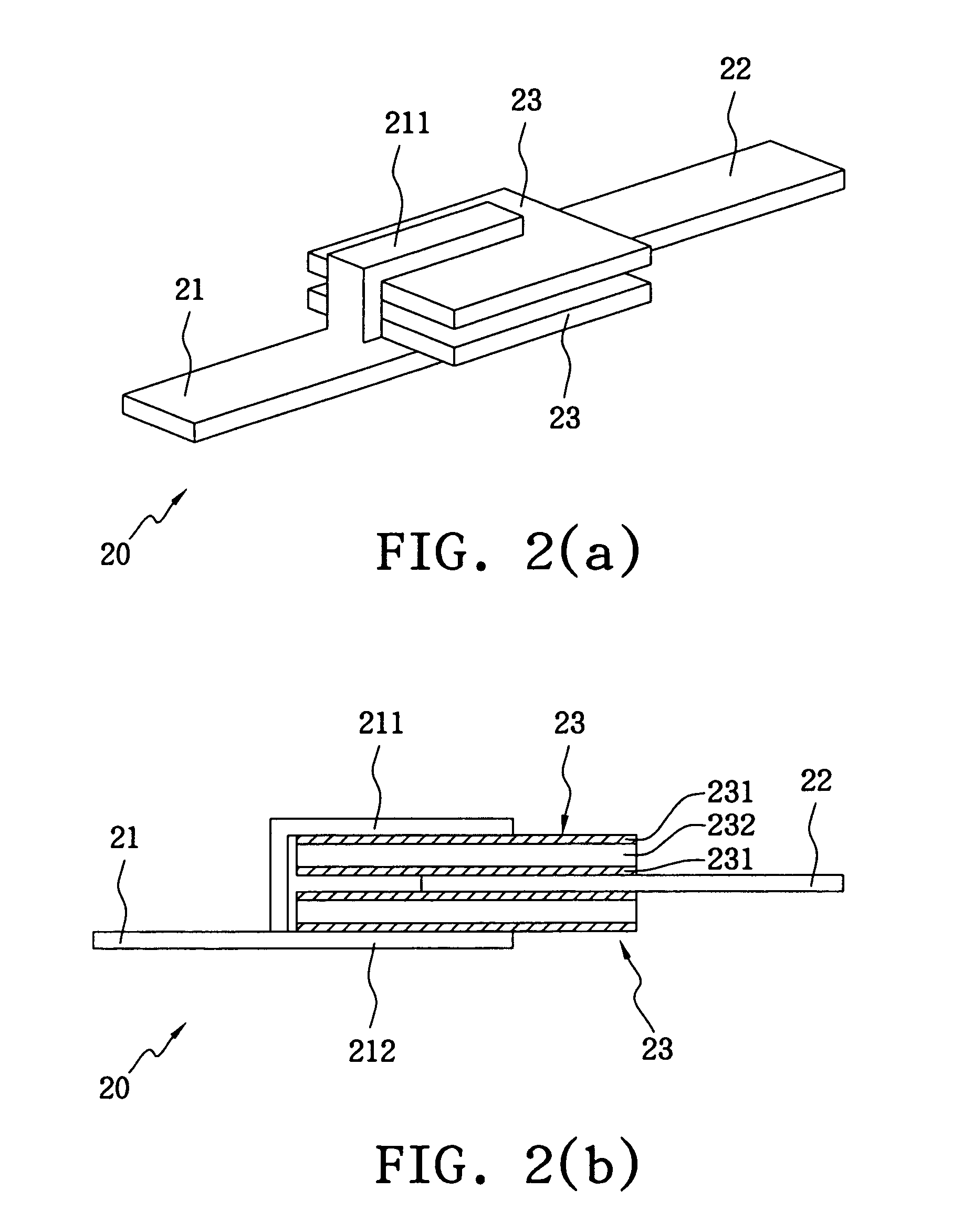
[0017]FIG. 2(a) illustrates an axial leaded over-current protection device 20 of an embodiment in accordance with the present invention. FIG. 2(b) illustrates the side view of the axial leaded over-current protection device 20. In view of shape, such axial leaded device is also named a strap device. The axial leaded over-current protection device 20, in the form of a strap, comprises a first terminal metal strip 21, a second terminal metal strip 22 and two PTC devices 23. The PTC device 23 is constituted of two electrode layers 231 and a PTC material layer 232 laminated therebetween. The PTC devices 23 are in the form of a stack strap structure. One end of the first terminal metal strip 21 diverges into two electrode strips 211 and 212, which are respectively connected to one of the electrode layers 231 (first electrode layer) of the two PTC devices 23. The second terminal metal strip 22 is connected to the other electrode layers 231 (second electrode layers) of the two PTC devices ...


PUM


Abstract

An axial leaded over-current protection device comprised of a plurality of PTC devices, a first terminal metal strip, and a second terminal metal strip. One end of the first terminal metal strip diverges into a plurality of electrode strips, and the plurality electrode strips are connected to an electrode layer of each PTC device. The second terminal metal strip is connected to the other electrode layer of each PTC device, i.e., the one not being connected to the first terminal metal strip. Accordingly, the first terminal metal strip and second terminal metal strip are respectively connected to the two electrode layers of each PTC device and become in parallel thereby, so that the resistance of the over-current protection device can be decreased.

Description

BACKGROUND OF THE INVENTION[0001](A) Field of the Invention[0002]The present invention is related to an axial leaded over-current protection device, more specifically, to an axial leaded over-current protection device of a positive temperature coefficient (PTC).[0003](B) Description of the Related Art[0004]The resistance of a positive temperature coefficient (PTC) conductive material is sensitive to temperature variation and can be kept extremely low during normal operation so that the circuit can operate normally. However, if an over-current or an over-temperature event occurs, the resistance will immediately increase to a high resistance state (e.g., above 104 ohm.) Therefore, the over-current will be eliminated and the objective to protect the circuit device will be achieved. Consequently, PTC devices have been commonly integrated into various circuitries so as to prevent the damage caused by over-current.[0005]FIG. 1(a) illustrates a perspective diagram of a known over-current p...

Claims


Application Information

Patent Timeline
Patent Type & Authority Patents(United States)
IPC IPC(8): H01C7/10H01C7/13H01C1/14H01C1/16H01C7/02
CPCH01C1/1406H01C7/02H01C1/16
Inventor WANG, SHAU CHEWCHEN, YI NUO
Owner POLYTRONICS TECH
Features
  • R&D
  • Intellectual Property
  • Life Sciences
  • Materials
  • Tech Scout
  • Unparalleled Data Quality
  • Higher Quality Content
  • 60% Fewer Hallucinations
Learn More