Color electrophoretic display device

a color display and electrophoretic technology, applied in the field of color display systems, can solve the problems of not being said to have a sufficient display quality level, unsatisfactory brightness and color sharpness, and the task of eyesight, so as to improve brightness and color sharpness, and improve display quality level

Inactive Publication Date: 2007-10-16
CANON KK
View PDF25 Cites 160 Cited by
  • Summary
  • Abstract
  • Description
  • Claims
  • Application Information

AI Technical Summary

Benefits of technology

[0026]Taking account of the problems discussed above, an object of the present invention is to provide a color electrophoretic display device, in particular, a reflection type color electrophoretic display device, having totally been improved in brightness and color sharpness and having achieved a display quality level closer to that of hard copy representation mediums.

Problems solved by technology

In liquid crystal display devices available at present, however, characters displayed on a screen may be viewed with difficulty depending on angles at which you look at the screen or under the influence of reflected light, and the task on eyesight which is caused by flickering, low luminance and so forth of a light source has not well been solved.
Also, in the display representation making use of a cathode ray tube, although it provides sufficient contrast and luminance compared with the liquid crystal display, it may cause flickering for example, and can not be said to have a sufficient display quality level compared with the hard copy representation discussed below.
In addition, its display units are so large and heavy as to have a very low portability.
Meanwhile, the hard copy representation has been considered to become unnecessary as information is made electronic, but in fact hard copies are still taken in a vast quantity.
Hence, the display on a screen may greatly task eyesight compared with the hard copy representation.
Thus, as long as any motion picture display or frequent rewriting is not required, the hard copy representation has various advantages different from the display representation, but has a disadvantage that paper is consumed in a large quantity.
This system is sometimes utilized as a display area of a prepaid card, but has problems such that the contrast is not so high and the writing and erasing can only be repeated a relatively small number of times, such as 150 to 500.
However, in such an electrophoretic display device (hereinafter often “vertical movement type electrophoretic display device”), a coloring material such as a dye or ions must be mixed in the insulating liquid, and the presence of such a coloring material tends to act as an unstable factor in electrophoretic movement because it brings about the delivering and receiving of additional electric charges, resulting in a lowering of performance, lifetime and stability as a display device in some cases.
However, in the additive mixture of color stimuli of the three primary colors, it is theoretically impossible to achieve brightness and color sharpness (inclusive of sufficient black display) simultaneously, and it is very difficult to materialize a reflection type display device having the display quality level the printed mediums can have.
A sufficient black is obtainable if black particles are used, but such a measure is insufficient in respect of the brightness and the color sharpness.
The brightness is improved if white particles are used, but, like the case shown in FIGS. 22A to 22D, any sharp color representation is not obtainable and also any sufficient black is not obtainable.
There, however, is a problem that the reflected light intensity in the black display (FIG. 23D) is 33% and only performance with a contrast of about 3 is obtainable.
However, their driving method in which particles arranged at display faces are separated and selected in a good precision only according to the magnitude of electrophoretic velocity is very difficult when gradational display is performed.
It is also considered that the operation of writing which consists of a plurality of steps is not adaptable to the active matrix drive making use of thin film transistors (also called TFTs) and hence may bring a low utility.

Method used


Image

  • Color electrophoretic display device
  • Color electrophoretic display device
  • Color electrophoretic display device

Examples


example 1

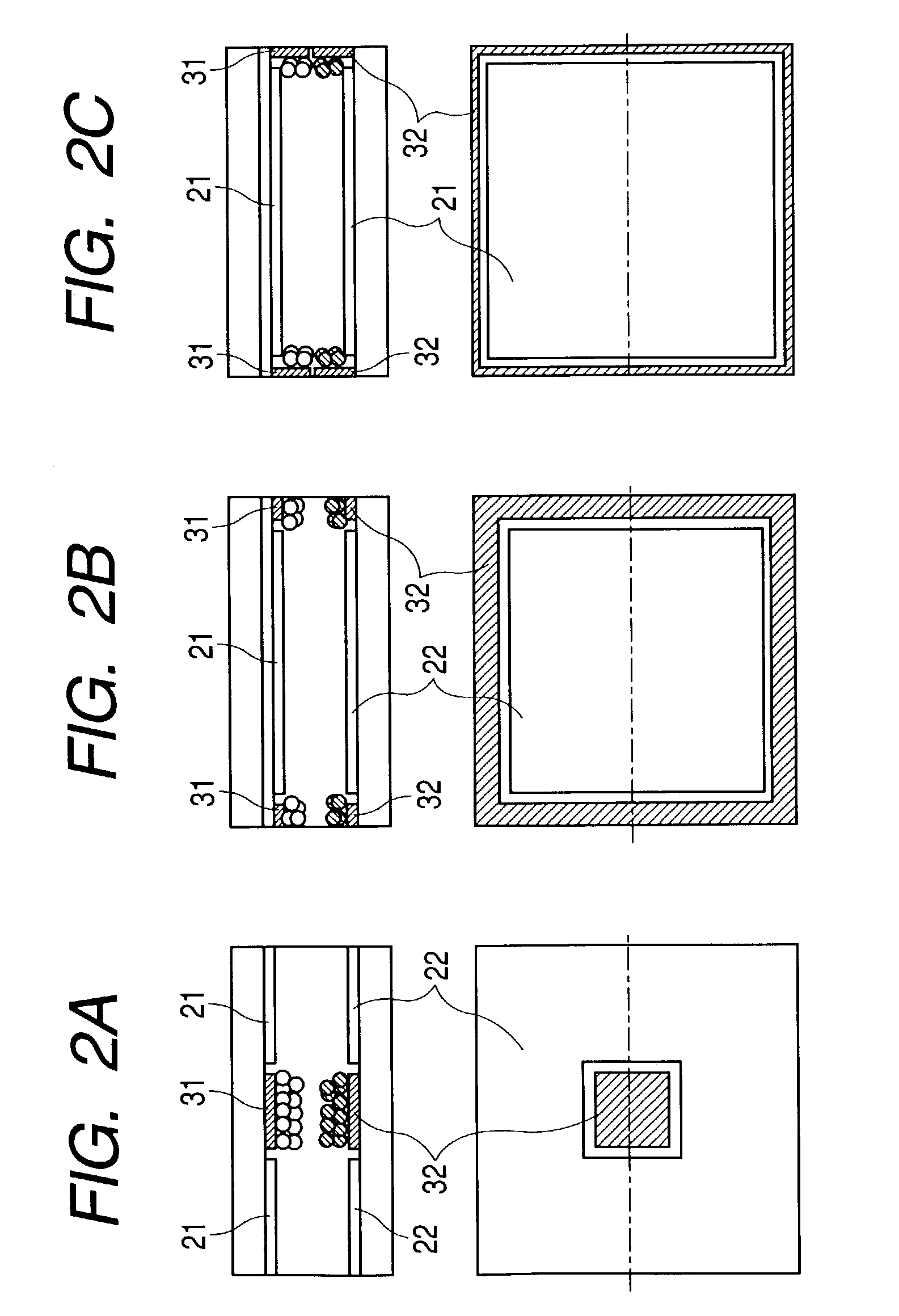
[0118]In this Example, described is an example of the structure, fabrication process and driving method of a color electrophoretic display-device in which pixels so structured that two unit cells are stacked (disposed in a stack) to constitute each pixel are arranged in a matrix. The display device to be fabricated have 100×100 pixels, and each pixel has a size of 200 μm×200 μm. FIGS. 14A to 14C present a cross sectional view (FIG. 14A) of areas corresponding to 2×2 pixels which are part of the display device, a plan view (FIG. 14B) along the line 14B-14B in FIG. 14A, and a plan view (FIG. 14C) along the line 14C-14C in FIG. 14A.

[0119]Partition walls 11 of 10 μm in width and 20 μm in height are disposed at pixel boundaries to divide the respective pixels and at the same time keep the distance between substrates constant. The unit cell structure in this Example corresponds to that shown in FIG. 2B. At the lower stage, a unit cell II containing an electrophoretic liquid in which two k...

example 2

[0134]In this Example, another example is described in regard to a color electrophoretic display device in which, like Example 1, pixels so structured that two unit cells are stacked (disposed in a stack) to constitute each pixel are arranged in a matrix.

[0135]The display device to be fabricated have 100×100 pixels, and each pixel has a size of 200 μm×200 μm. FIGS. 16A to 16C present a cross sectional view (FIG. 16A) of areas corresponding to 2×2 pixels which are part of the display device, a plan view (FIG. 16B) along the line 16B-16B in FIG. 16A, and a plan view (FIG. 16C) along the line 16C-16C in FIG. 16A.

[0136]The unit cell structure in this Example corresponds to that shown in FIG. 3B. At both the lower stage and the upper stage, a unit cell II containing an electrophoretic liquid in which two kinds of colored electrophoretic particles having different colors and charge characteristics have been dispersed, two display electrodes and two collection electrodes is disposed.

[0137]...

example 3

[0148]In this Example, described is a color electrophoretic display device in which pixels so structured that three unit cells are disposed in parallel to constitute each pixel are arranged in a matrix. The display device to be fabricated have 100×100 pixels, and each pixel has a size of 300 μm×300 μm. FIGS. 18A and 18B present a cross sectional view (FIG. 18A) of areas corresponding to 2×2 pixels which are part of the display device, and a plan view (FIG. 18B) along the line 18B-18B in FIG. 18A.

[0149]Each pixel in this Example is constituted of three unit cells of 100 mm in width and 300 μm in length which are disposed in parallel, and contains an electrophoretic liquid in which two kinds of colored electrophoretic particles have been dispersed. The respective colored electrophoretic particles are translucent polymer particles colored with dyes. A first cell (left side), a second cell (middle) and a third cell (right side) are filled with insulating liquids in which yellow positive...


PUM

PropertyMeasurementUnit
electrode potentialsaaaaaaaaaa
voltageaaaaaaaaaa

Abstract

An electrophoretic display device includes unit cells each containing i) two sets of display electrodes and a collection electrode and ii) two kinds of translucent colored electrophoretic particles having charge polarities different from each other. The unit cells are constructed so that the two display electrodes are superimposingly disposed to display the stated display color by the principle of subtractive mixture of color stimuli of the colored electrophoretic particles present on the display electrodes. Three unit cells are adjacently disposed in a same plane to form a pixel, and combinations of colors of the two kinds of translucent colored electrophoretic particles in each of the three unit cells forming the pixel are respectively one of the three primary colors and a color which provides black by subtractive mixture with one of the three primary colors.

Description

BACKGROUND OF THE INVENTION[0001]1. Field of the Invention[0002]This invention relates to a color display system in electrophoretic display devices.[0003]2. Related Background Art[0004]In recent years, with advancement of information machinery, the quantity of data of various information is becoming larger and larger, and the information is also outputted in various forms. The outputting of information is commonly roughly grouped into “display representation” making use of a cathode ray tube, a liquid crystal display panel or the like and “hard copy representation” on paper by means of a printer or the like.[0005]In the display representation, there is an increasing need for display devices of low power consumption and small thickness. In particular, liquid crystal display devices have energetically been developed and commercialized as display devices adapted for such need. In liquid crystal display devices available at present, however, characters displayed on a screen may be viewe...

Claims


Application Information

Patent Timeline
Patent Type & Authority Patents(United States)
IPC IPC(8): G09G3/34G02B26/00G02B5/20G02F1/167
CPCG02F1/167G09G3/3446G02F2203/34G09G2310/061G09G2300/0452G09G2300/08G09G2310/06G09G2300/023
Inventor KISHI, ETSURO
Owner CANON KK
Why Eureka
Try Eureka