Optical measuring device
- Summary
- Abstract
- Description
- Claims
- Application Information
AI Technical Summary
Benefits of technology
Problems solved by technology
Method used
Image

Examples
embodiment 1
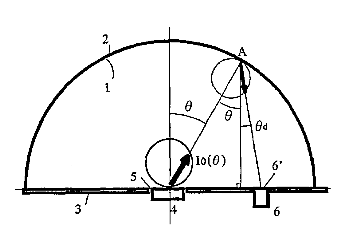
[0060]A first preferred embodiment of an optical measuring device according to the present invention will be described with reference to FIG. 1.
[0061]The optical measuring device of this preferred embodiment is a total luminous flux measuring device that includes an integrating hemisphere 2, of which the inner wall surface functions as a light diffuse reflective surface 1, and a plane mirror 3 to close the opening of the integrating hemisphere 2. The light diffuse reflective surface 1 is formed by either coating the inner surface of the integrating hemisphere 2 with a diffusive material that diffuses the radiation to be measured or processing the inner surface of the integrating hemisphere 2. The plane mirror 3 has a central opening that functions as either a light entering window or a light source fitting hole 5 and an observation window 6′ that enables a photodetector 6 to take measurements. The center of radius of curvature of the hemisphere 2 is defined within the central openin...
embodiment 2
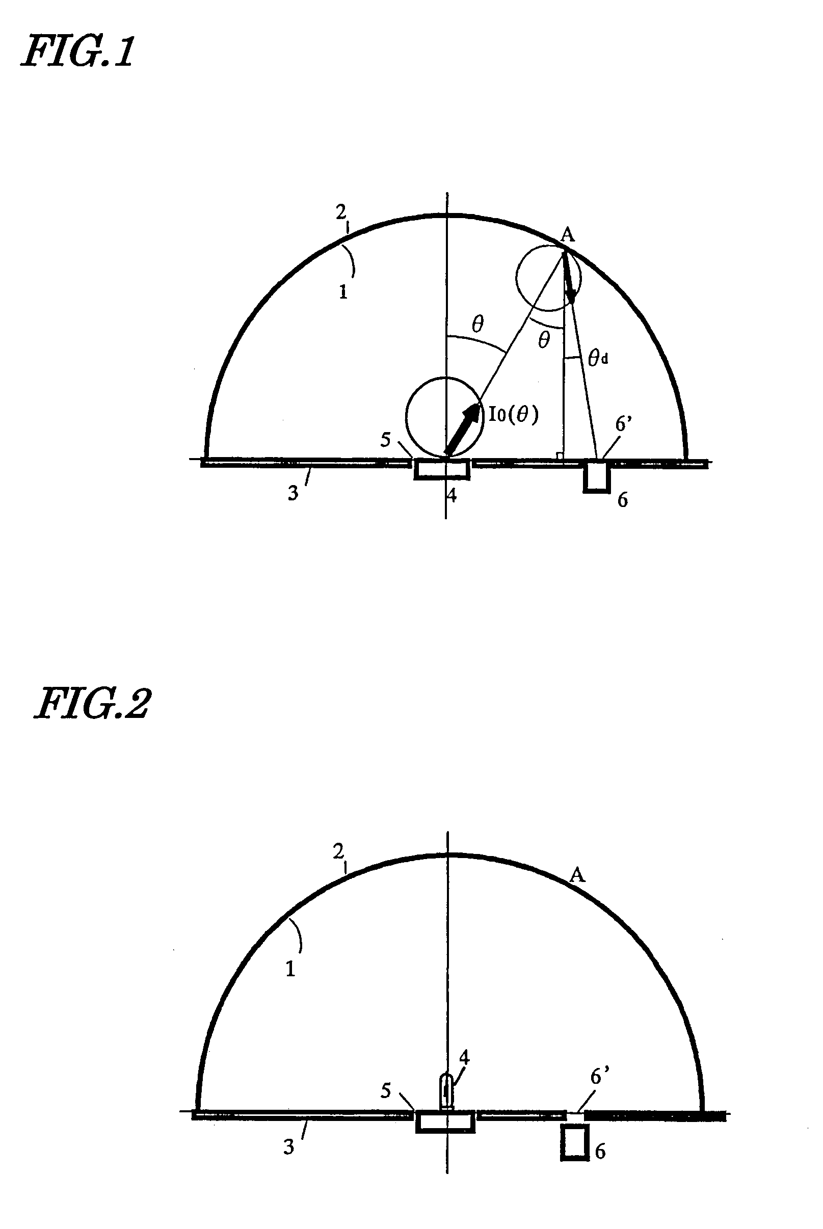
[0085]A second preferred embodiment of an optical measuring device according to the present invention will be described with reference to FIG. 2.
[0086]The photometer shown in FIG. 2 includes an integrating hemisphere 2, of which the inner wall surface functions as a light diffuse reflective surface 1, and a plane mirror 3, which is arranged so as to close the opening of the integrating hemisphere 2, including the center of curvature thereof. A light source 4, of which the total luminous flux should be measured, is fitted into a light source fitting window 5, which is arranged at the center of curvature of the integrating hemisphere 2 on the surface of the plane mirror 3. Meanwhile, a photodetector 6 is fitted into an observation window 6′ on the surface of the plane mirror 3 but is arranged such that the light source 4 is invisible to the photodetector 6.
[0087]Next, the operating principle of the photometer of this preferred embodiment will be described.
[0088]The light source 4 of t...
embodiment 3
[0111]A third preferred embodiment of an optical measuring device according to the present invention will be described with reference to FIG. 5.
[0112]The device of this preferred embodiment (total luminous flux measuring device) includes an integrating hemisphere 2, of which the inner wall surface functions as a light diffuse reflective surface 1, and a plane mirror 3, which is arranged so as to close the opening of the integrating hemisphere 2, including the center of curvature thereof. A light source 4, of which the total luminous flux should be measured, is fitted into a light source fitting window 5, which is arranged at the center of curvature of the integrating hemisphere 2 on the surface of the plane mirror 3. In this preferred embodiment, a luminometer 8 measures the luminance at an infinitesimal surface element A on the inner wall of the integrating hemisphere 2 through an observation window 6′ on the plane mirror 3.
[0113]Next, the operating principle of the photometer of t...
PUM
 Abstract
Description
Claims
Application Information