Confocal optical scanner

a confocal optical scanner and optical system technology, applied in the direction of optical elements, fluorescence/phosphorescence, instruments, etc., can solve the problems of low s/n ratio, dark fluorescent image obtained, and inability to reflect a considerable part of proper fluorescence emitted from the sample by the multi-wavelength dichroic mirror. to achieve the effect of enhanced light receiving efficiency of fluorescen

Inactive Publication Date: 2007-10-16
YOKOGAWA ELECTRIC CORP
View PDF9 Cites 7 Cited by
  • Summary
  • Abstract
  • Description
  • Claims
  • Application Information

AI Technical Summary

Benefits of technology

[0021]An object of the invention is to provide a confocal optical scanner using one high reflection mirror, without using a plurality of dichroic mirrors by exchange, in which a polychromatic fluorescent image is measured at the same time and the light receiving efficiency of fluorescence is enhanced.

Problems solved by technology

However, the conventional confocal optical scanner has the following problems.(1) This multi-wavelength dichroic mirror cannot reflect a considerable part of proper fluorescence emitted from the sample.
The efficiency is very bad with the characteristic of such a multi-wavelength dichroic mirror, so that the obtained fluorescent image is dark, and the S / N ratio is low.(2) A dedicated filter is required for each kind of fluorescent reagent.
It is undesirable in respects of cost, inventory, exchange time and contamination at exchange time.
Also, when the filter is exchanged, a large image deviation may occur as a significant problem when the superposed image is observed.(3) When the transmitted image or the inverted fluorescent image of blue nucleus staining with 4′,6-diamidino-2-phenylindole, dihydrochioride (Dapi) color pigment is superposed on the confocal fluorescent image to be measured, a blue image, as indicated by the one dot chain line in FIG. 2A, of the transmitted image or the inverted fluorescent image is cut by the multi-wavelength dichroic mirror.
Therefore, the correct measurement is not allowed, and the superposed image is dark.

Method used


Image

  • Confocal optical scanner
  • Confocal optical scanner
  • Confocal optical scanner

Examples


Embodiment Construction

[0033]The present invention will be described in detail with reference to the accompanying drawings.

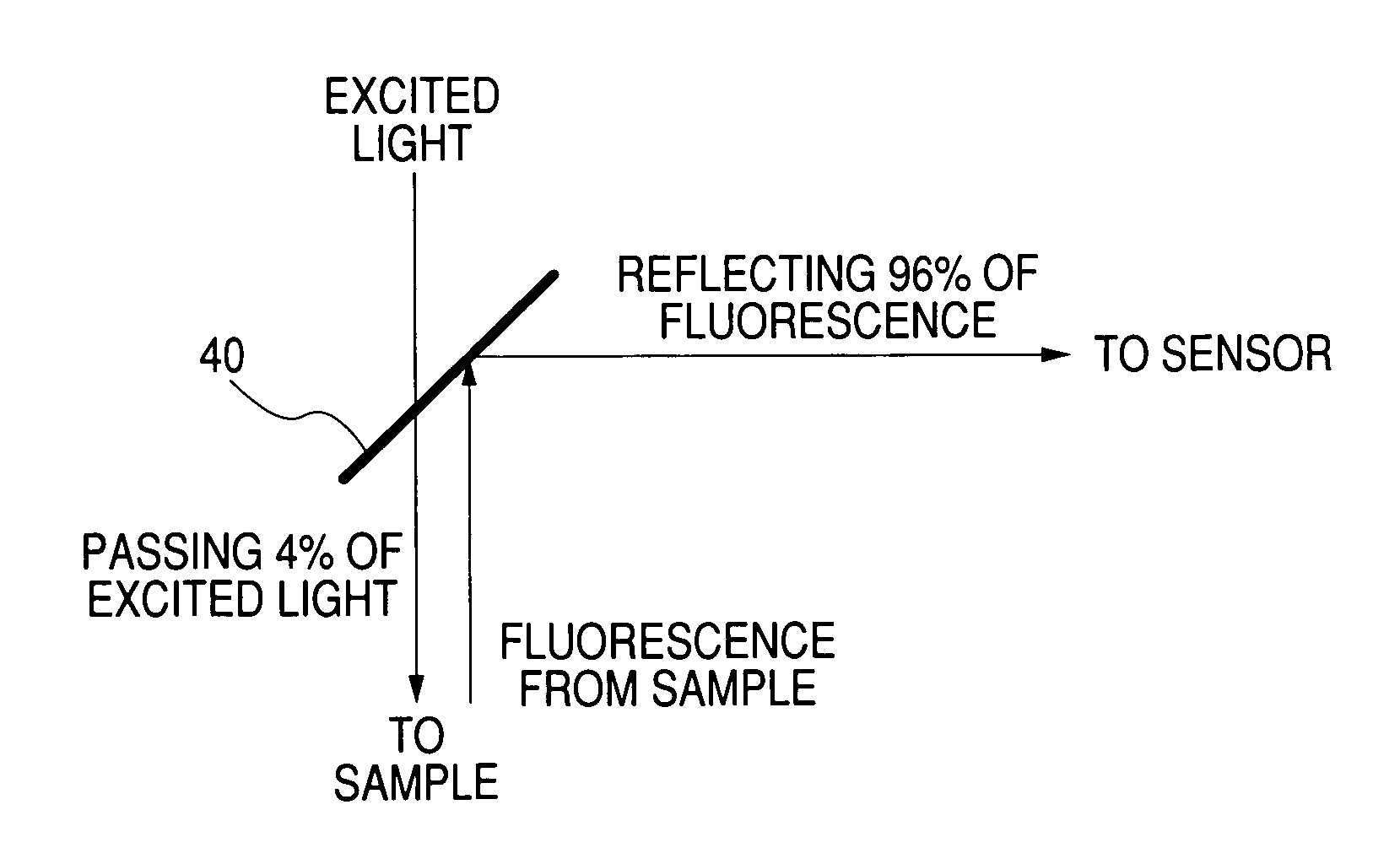
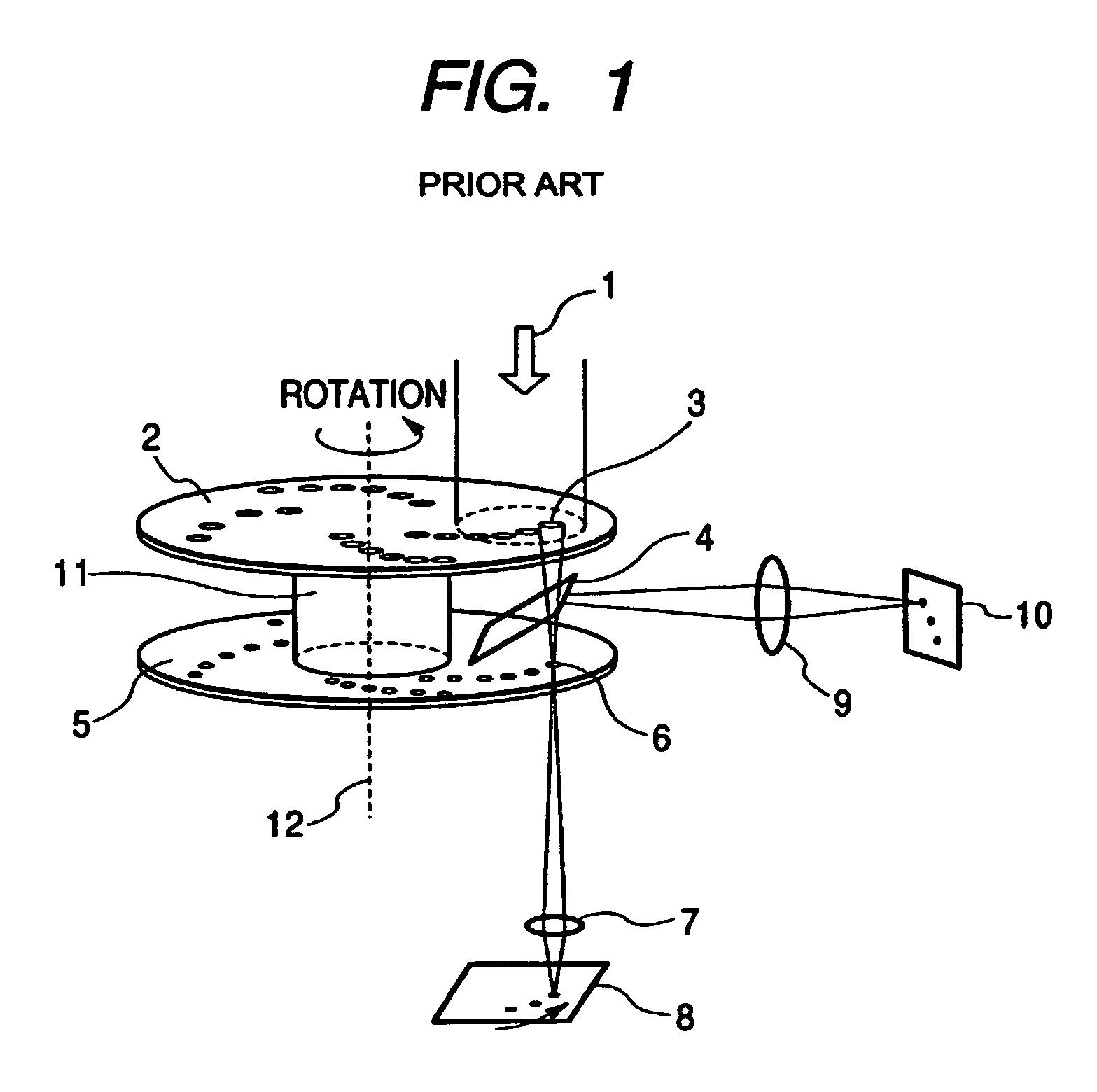
[0034]FIG. 3 is a schematic diagram showing an embodiment of a confocal optical scanner according to the invention. In FIG. 3, the same or like elements are designated by the same numerals as in FIG. 1, and not described here. A point different from FIG. 1 is a high reflection mirror 40.

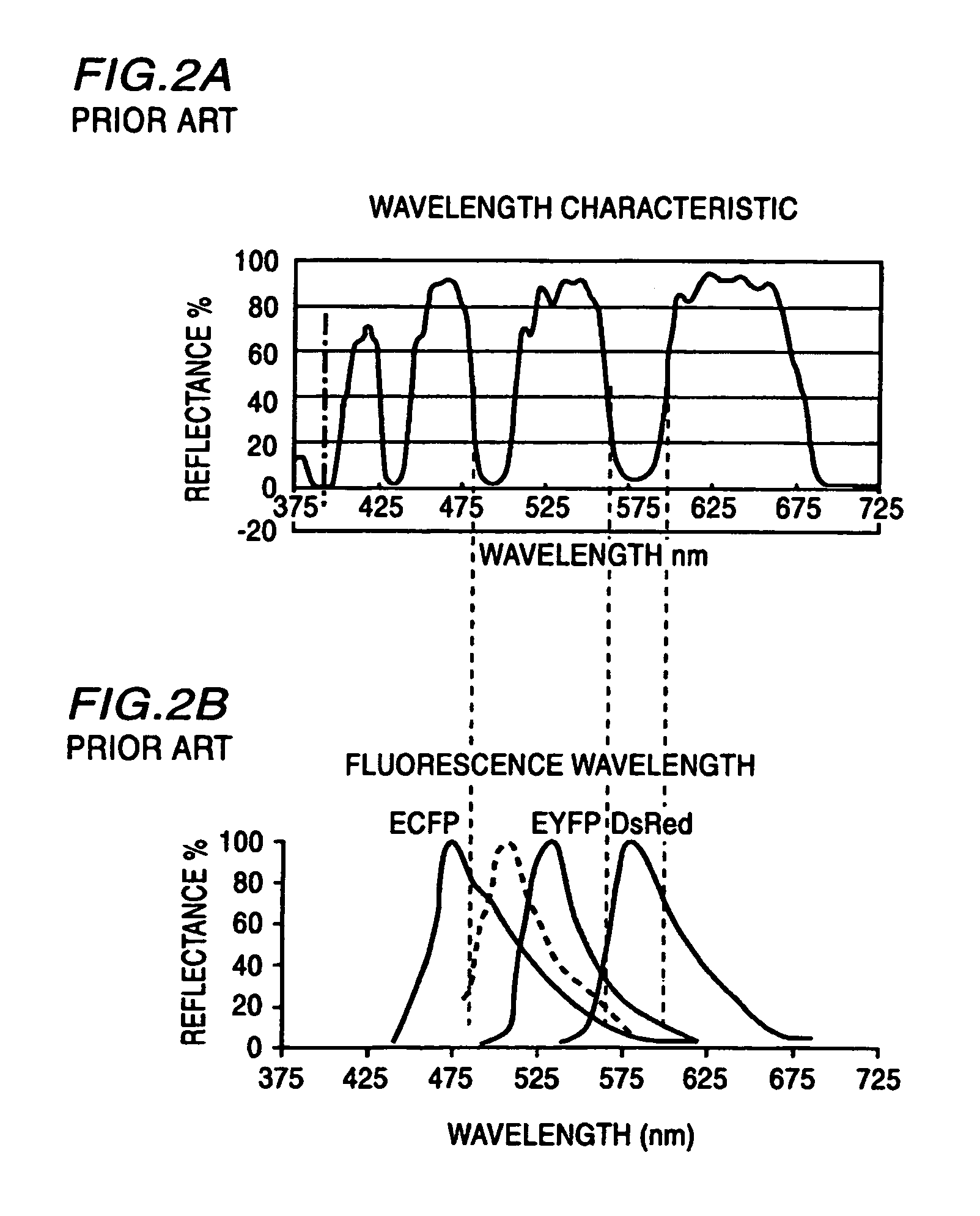
[0035]A reflectance of the high reflection mirror 40 is about 96% over the entire wavelength region (measured wavelength region) used, as shown in FIG. 4. The measured wavelength region consists of an excited light wavelength region and a fluorescent wavelength region. Moreover, the measured wavelength region may include a wavelength region of transmitted or inverted fluorescent image.

[0036]According to the high reflection mirror, 4% of an excited light 1 passes through the high reflection mirror 40 to be radiated onto a sample 8. On the other hand, 96% of a fluorescence from the sample 8 is reflected ...


PUM

PropertyMeasurementUnit
reflectanceaaaaaaaaaa
fluorescence reflectanceaaaaaaaaaa
wavelengthaaaaaaaaaa

Abstract

A confocal optical scanner of Nipkow disk type for measuring a sample, in which each component of two or more color pigments, has a high reflection mirror for separating an excited light to be radiated onto the sample and a fluorescence emitted from the sample, wherein a reflectance of the high reflection mirror is from 80% to 100% in a measured wavelength region including at least an excited light wavelength region and a fluorescence wavelength region. Thereby, the confocal optical scanner capable of measuring a polychromatic fluorescent image at the same time is realized with the enhanced light receiving efficiency of fluorescence, using one high reflection mirror without using a plurality of dichroic mirrors by exchange.

Description

BACKGROUND OF THE INVENTION[0001]1. Field of the Invention[0002]The present invention relates to an optical system in a confocal optical scanner, and particularly to improvements in a dichroic mirror for measuring a plurality of kinds of fluorescence (also referred to as a polychromatic fluorescence) emitted from a sample at the same time and enhancement of the fluorescence efficiency.[0003]2. Description of the Related Art[0004]Conventionally, a confocal optical scanner used with a microscope has been well known (e.g., refer to C. Genka, K. Ishida, K. Ichimori, Y. Hirota, T. Tanaami, H. Nakazawa, “Visualization of biphasic Ca2+ diffusion from cytosol to nucleus in contracting adult rat cardiac myocytes with an ultra-fast confocal imaging system”, Cell Calcium, Volume 25, Issue 3, P. 199-208). FIG. 1 is a schematic diagram of the principle of the confocal optical scanner of this kind. A laser 1 as an excited light is converged into individual light fluxes by each microlens 3 dispose...

Claims


Application Information

Patent Timeline
Patent Type & Authority Patents(United States)
IPC IPC(8): G02B27/14G02B21/00G02B26/02G01N21/64
CPCG02B21/0024G02B21/0076G02B21/0044
Inventor MIKURIYA, KENTATANAAMI, TAKEOSEKI, NAOKINAGAI, TAKEHARUMIYAWAKI, ATSUSHI
Owner YOKOGAWA ELECTRIC CORP
Why Eureka
Try Eureka