Bi-directional optical communication module

a communication module and bi-directional technology, applied in the direction of optical elements, instruments, semiconductor lasers, etc., can solve the problems of difficult mounting accuracy in the rotational direction () of the wdm filter b>56/b>, and achieve the effect of increasing the production yield of the optical module and reducing the difficulty of mounting accuracy

Inactive Publication Date: 2010-01-12
LAPIS SEMICON CO LTD
View PDF2 Cites 0 Cited by
  • Summary
  • Abstract
  • Description
  • Claims
  • Application Information

AI Technical Summary

Benefits of technology

[0015]It is an object of the present invention to provide an optical communication module, in which light receiving efficiency of a PD can be improved without deterioration of a receiving sensitivity of the PD.
[0018]Here, it is important to control a planar shape of the light receiving portion of the optical detector without change of the area of the light receiving portion. According to the present invention, it is not necessary to incline a photo detector to control a projected area of a light receiving portion.
[0019]According to the present invention, a tolerance of mounting accuracy of a wavelength branching filter in a rotational direction becomes larger. As a result, a production yield of an optical module is increased. Further, a PD chip for high frequency can be fabricated without deterioration of mounting tolerance, which has trade-off relation to a light receiving area of a PD.

Problems solved by technology

Mounting accuracy in a rotational direction (θ) of the WDM filter 56 is difficult but very important.
However, if a receiving area is enlarged, a capacity of the PD 54 would be increased, and therefore, technical specification (requirements or regulations) including minimum reception sensitivity and maximum capacitance would be out of acceptable range.

Method used


Image

  • Bi-directional optical communication module
  • Bi-directional optical communication module
  • Bi-directional optical communication module

Examples


first preferred embodiment

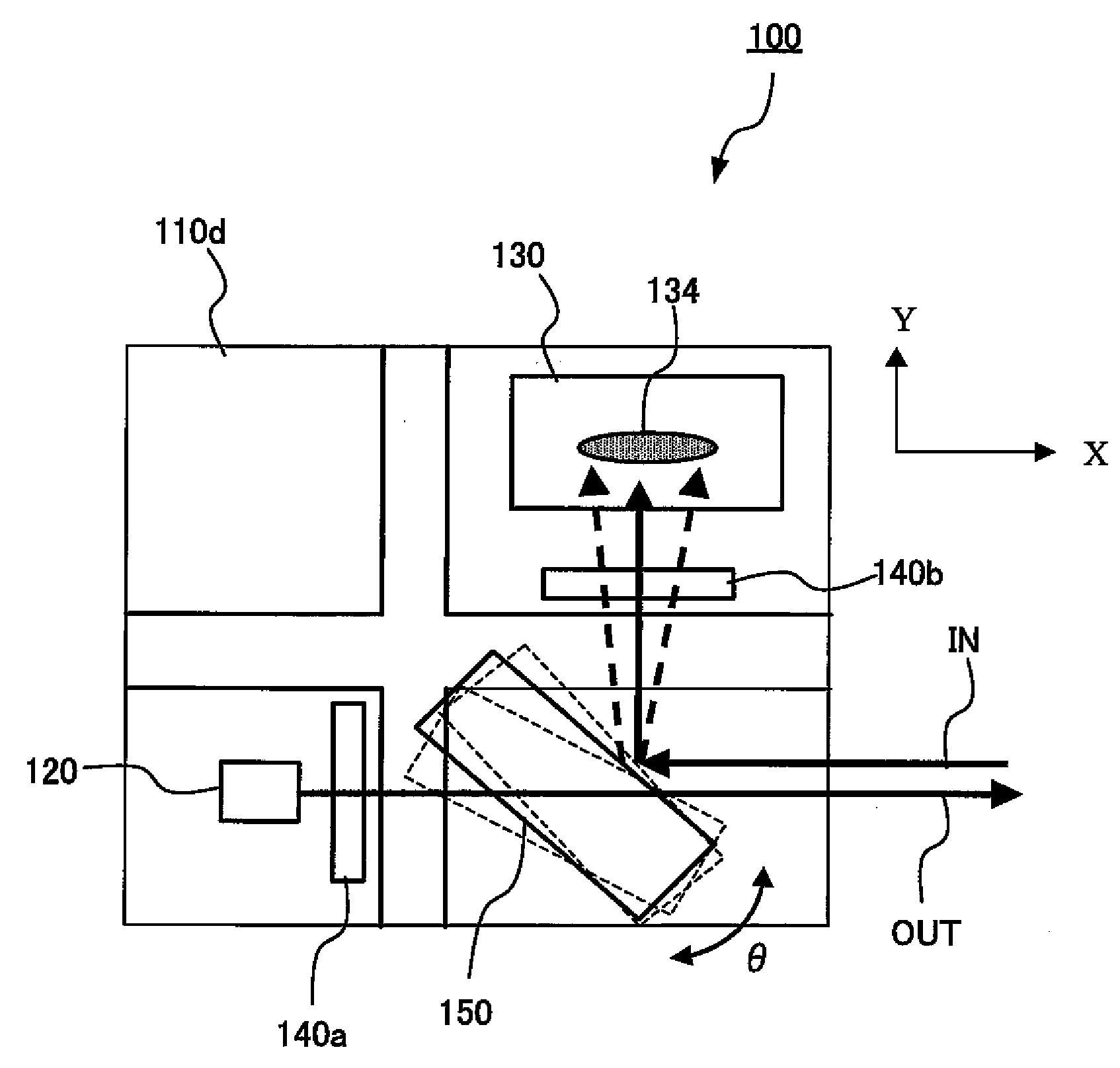
[0037]FIG. 3 is a perspective view illustrating a bi-directional optical communication module according to a first preferred embodiment of the present invention. FIG. 4 is a plane view illustrating a bi-directional optical communication module shown in FIG. 3.

[0038]An optical module 100 according to the present embodiment, a substrate 110 having V-shaped grooves 110a and 110b is prepared. On the substrate 110, a laser diode (LD) 120 functioning as a light emitting device, a photodiode (PD) 130 functioning as a light receiving device, lens elements 140a and 140b, and a wavelength branching filter (WDM filter) 150 are mounted.

[0039]The substrate 110 may be of a silicon substrate. The V-shaped grooves 110a and 110b have a cross-section of V-shape. The substrate 110 is also provided with a rectangle groove 110c. The substrate 110 includes a non-mounting region 110d, and a stepped region 110e on which the wavelength branching filter 150 is mounted. Electrode pads 112 are formed on the su...

second preferred embodiment

[0064]A second preferred embodiment of the present invention is now described, in which the difference from the first preferred embodiment is mainly described. FIG. 6 is a perspective view illustrating a bi-directional optical communication module according to a second preferred embodiment of the present invention. FIG. 7A is a perspective view illustrating a PD used in a bi-directional optical communication module, shown in FIG. 6. FIG. 7B is a cross-sectional view illustrating a PD used in a bi-directional optical communication module, shown in FIG. 6.

[0065]An optical module 200 according to the present embodiment, a substrate 110 having V-shaped grooves 110a and 110b is prepared. On the substrate 110, a laser diode (LD) 120 functioning as a light emitting device, a photodiode (PD) 230 functioning as a light receiving device, lens elements 140a and 140b, and a wavelength branching filter (WDM filter) 150 are mounted.

[0066]The PD 230 is a light receiving element and is shaped to be...


PUM


Abstract

An optical communication module includes a base substrate; a wavelength branching filter arranged on the base substrate, in which a light is allowed to go through or be reflected according to a wavelength thereof; a photodetector arranged on the base substrate to receive a light passed through the wavelength branching filter and to convert the light into an electric signal; and a light emitting device arranged on the base substrate to provide a transmission light. The transmission light is outputted through the wavelength branching filter. The optical detector comprises a light receiving portion which is formed to have a first length and a second length, which is shorter than the first length. The first length of the light receiving portion is perpendicular to an optical axis of an input light on a plane parallel to a surface of the substrate, and a second length of the light receiving portion is parallel to the optical axis of the input light.

Description

CROSS REFERENCE TO RELATED APPLICATION[0001]This application claims the priority of Application No. 2008-033385, filed Feb. 14, 2008 in Japan, the subject matter of which is incorporated herein by reference.TECHNICAL FIELD OF THE INVENTION[0002]The present invention relates to an optical communication module used as a communication device. The present invention relates in particular to the optical communication module, in which optical elements for transmission and reception are mounted as a whole on a substrate using a surface mounting method.[0003]In an optical communication network represented by Fiber To The Home (FTTH), a bi-directional optical communication system has become widely used. The bi-directional optical communication system connects a communication office with a user through a single optical fiber and bi-directionally communicates using two kinds of light with different wavelengths as a transmission signal and a reception signal, respectively.[0004]According to such...

Claims


Application Information

Patent Timeline
Patent Type & Authority Patents(United States)
IPC IPC(8): G02B6/26G02B6/36H04B10/00G02B6/42H01L31/02H01S5/022
CPCG02B6/4246
Inventor UEKAWA, MASAHIRO
Owner LAPIS SEMICON CO LTD
Why Eureka
Try Eureka