Broadcast data receiver apparatus and method for controlling power supply

Active Publication Date: 2007-10-16
ARRIS ENTERPRISES LLC
View PDF13 Cites 12 Cited by
  • Summary
  • Abstract
  • Description
  • Claims
  • Application Information

AI Technical Summary

Benefits of technology

[0006]The aim of the present invention is to provide broadcast data receiver apparatus for providing a power supply to an LNB in a manner which a

Problems solved by technology

However due to power dissipation which occurs, the actual levels which are required to be

Method used


Image

  • Broadcast data receiver apparatus and method for controlling power supply
  • Broadcast data receiver apparatus and method for controlling power supply

Examples


Embodiment Construction

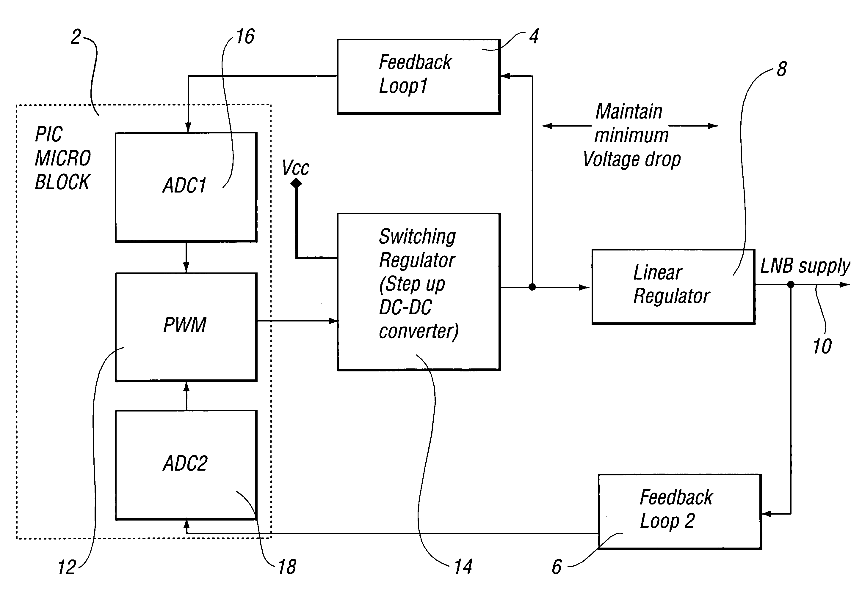
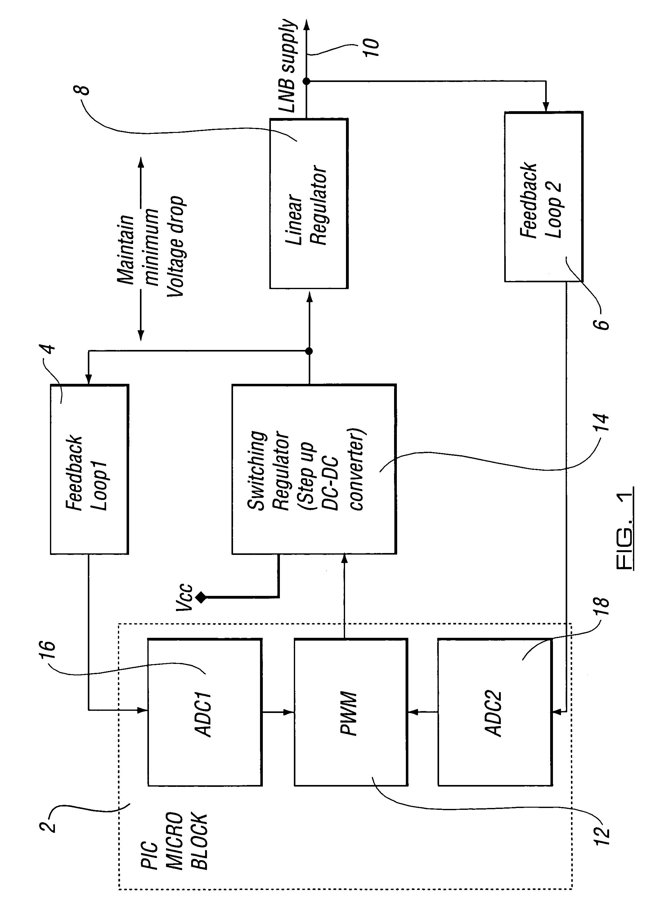
[0014]Referring now to FIG. 1 there is shown a programmable microcontroller block (PIC) microblock 2 which receives data from first and second feedback loops 4, 6 respectively in order to maintain minimum voltage drop at the linear regulator 8 to the LNB supply 10.

[0015]In accordance with the invention, a relatively low voltage rail within a BDR can be used to generate the necessary voltages required to operate an LNB.

[0016]By closely monitoring the voltage, minimum dissipation within the LNB regulator circuit can be obtained so that the BDR uses less power and dissipates less heat. By using a single voltage rail to generate the voltage, rather than a double or a number of voltage rails arrangement as is conventionally the case, up to two voltage rails can be saved from the power supply in the BDR. The saved voltage rails can be removed to save money or alternatively they can be used to generate lower core voltages such as 2.1v or 1.8v which can also increase overall efficiency and ...


PUM


Abstract

Broadcast data receiver apparatus is provided. The apparatus includes a broadcast data receiver (BDR) connected to at least one LNB. The BDR provides a power supply to allow operation of the LNB. At least two analogue to digital converter sampling points are provided to allow the input and output voltages to be measured at the LNB, thereby allowing the voltage drop across a linear regulator (8) of the LNB to be assessed. Control means are provided to control the power supply from the BDR to the LNB in response to the voltage measurements obtained.

Description

CROSS-REFERENCE TO RELATED APPLICATION[0001]This application claims priority to British Patent Application No. 0107045.7 filed 21 Mar. 2001.BACKGROUND OF THE INVENTION[0002]The invention which is the subject of this application relates to broadcast data receiver apparatus for the control and provision of power supply to components of a broadcast data receiving system which utilizes a Low Noise Block (LNB) either singly, or in combination, as part of the data receiving apparatus.[0003]Typically, broadcast data receiving apparatus incorporates a means for receiving data which is broadcast from a remote location (the head end) to a number of locations, each equipped with the apparatus. In one system, the data is broadcast via a satellite transmission system whereby the data is received at a number of premises, each equipped with an antenna which includes at least one LNB for the reception of data carried at certain frequencies. When received by the LNB, the data passes to a Broadcast d...

Claims


Application Information

Patent Timeline
IPC IPC(8): H01Q11/12H04H1/00H04H20/00H04H40/90H04N5/44H04N5/63H04N7/20
CPCH04N5/4401H04N21/4436H04H40/90H04N7/20H04N5/63H04N21/426
Inventor SMITH, MARKYATES, PHILIPFAULKNER, COLIN
Owner ARRIS ENTERPRISES LLC
Why Eureka
Try Eureka