Method and apparatus for operating an intercooler for a gas turbine engine

a technology of gas turbine engine and intercooler, which is applied in the field of gas turbine engine, can solve the problems of reducing the operating efficiency of the gas turbine engine, and the heat rejected by the intercooler is not utilized by so as to facilitate facilitating increasing the operating efficiency of the gas turbine engine, and facilitating the effect of increasing the operating temperature of the working fluid

Active Publication Date: 2007-10-23
GENERAL ELECTRIC CO
View PDF18 Cites 59 Cited by
  • Summary
  • Abstract
  • Description
  • Claims
  • Application Information

AI Technical Summary

Benefits of technology

[0005]In one aspect, a method for operating a gas turbine engine is provided. The method includes channeling compressed airflow discharged from a first compressor through an intercooler having a cooling medium flowing therethrough, channeling a working fluid through the intercooler to facilitate increasing an operating temperature of the working fluid, and channeling the discharged working fluid to a combustor to facilitate increasing an operating efficiency of the gas turbine engine.
[0006]In another aspect, an intercooler system for a gas turbine engine that includes at least a first compressor, a second compressor, a combustor, and a turbine is provided. The intercooler system includes an intercooler coupled downstream from the first compressor such that compressed air discharged from the first compressor is routed therethrough, and a heating system in flow communication with the intercooler. The heating system is configured to channel a working fluid through the intercooler to facilitate increasing an operating temperature of the working fluid, and channel the discharged working fluid to the combustor to facilitate increasing a thermal efficiency of the gas turbine engine.
[0007]In a further aspect, a gas turbine engine is provided. The gas turbine engine includes a first compressor, a second compressor downstream from the first compressor, a combustor downstream from the second compressor, a turbine coupled in flow communication with the combustor, and an intercooler system in flow communication with the intercooler. The intercooler system includes an intercooler coupled downstream from the first compressor such that compressed air discharged from the first compressor is routed therethrough, and a heating system in flow communication with the intercooler. The heating system is configured to channel a working fluid through the intercooler to facilitate increasing the operating temperature of the working fluid, and channel the discharged working fluid to the combustor to facilitate increasing a thermal efficiency of the gas turbine engine

Problems solved by technology

Intercooler gas turbine engines may include either the single annular combustor, a can-annular combustor, or the DLE combustor, however, injecting water into such an engine to facilitate reducing NOx emissions, may actually decrease the operating efficiency of the gas turbine engine.
Moreover, although using an intercooler facilitates increasing the efficiency of the engine while reducing the quantity of work performed by the high pressure compressor, the heat rejected by the intercooler is not utilized by the gas turbine engine.

Method used


Image

  • Method and apparatus for operating an intercooler for a gas turbine engine
  • Method and apparatus for operating an intercooler for a gas turbine engine
  • Method and apparatus for operating an intercooler for a gas turbine engine

Examples


Embodiment Construction

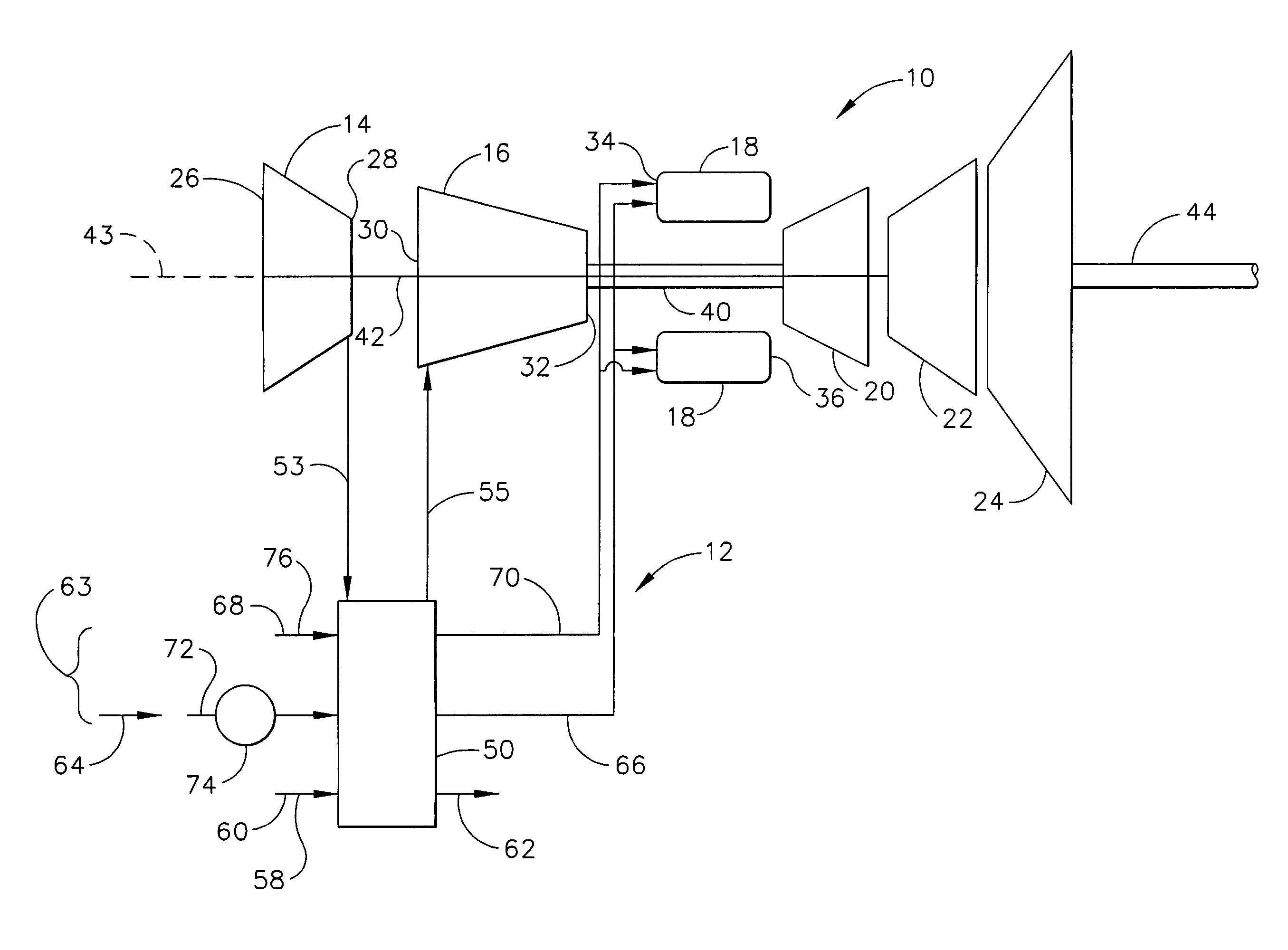
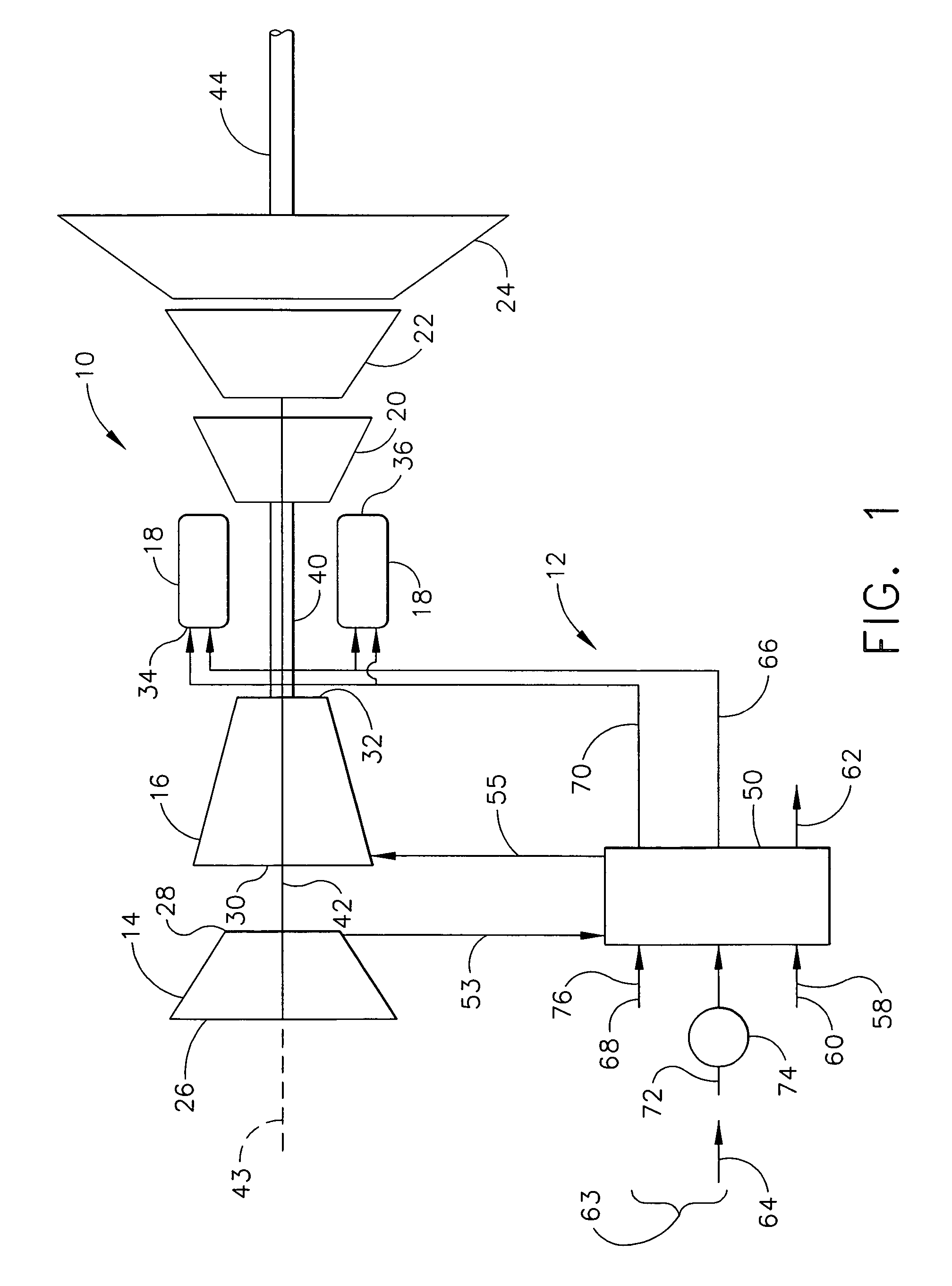
[0010]FIG. 1 is a block diagram of a gas turbine engine 10 including an intercooler system 12. Gas turbine engine 10 includes, in serial flow relationship, a low pressure compressor or booster 14, a high pressure compressor 16, a combustor 18, a high pressure turbine 20, an intermediate turbine 22, and a power turbine or free turbine 24. Low pressure compressor or booster 14 has an inlet 26 and an outlet 28, and high pressure compressor 16 includes an inlet 30 and an outlet 32. Combustor 18 has an inlet 34 that is substantially coincident with high pressure compressor outlet 32, and an outlet 36. In one embodiment, combustor 18 is an annular combustor. In another embodiment, combustor 18 is a dry low emissions (DLE) combustor. In a further embodiment, combustor 18 is a can-annular combustor.

[0011]High pressure turbine 20 is coupled to high pressure compressor 16 with a first rotor shaft 40, and intermediate turbine 22 is coupled to low pressure compressor 14 with a second rotor shaf...


PUM


Abstract

A method for operating a gas turbine engine includes channeling compressed airflow discharged from a first compressor through an intercooler having a cooling medium flowing therethrough, channeling a working fluid through the intercooler to facilitate increasing an operating temperature of the working fluid, and channeling the discharged working fluid to a combustor to facilitate increasing an operating efficiency of the gas turbine engine.

Description

BACKGROUND OF THE INVENTION[0001]This invention relates generally to gas turbine engines, and more specifically to methods and apparatus for operating gas turbine engines.[0002]Gas turbine engines generally include, in serial flow arrangement, a high-pressure compressor for compressing air flowing through the engine, a combustor in which fuel is mixed with the compressed air and ignited to form a high temperature gas stream, and a high pressure turbine. The high-pressure compressor, combustor and high-pressure turbine are sometimes collectively referred to as the core engine. At least some known gas turbine engines also include a low-pressure compressor, or booster, for supplying compressed air to the high pressure compressor.[0003]Gas turbine engines are used in many applications, including in aircraft, power generation, and marine applications. The desired engine operating characteristics vary, of course, from application to application. More particularly, within some applications...

Claims


Application Information

Patent Timeline
Patent Type & Authority Patents(United States)
IPC IPC(8): F02C7/143F02C3/30F02C7/224F02C7/08F02G5/00
CPCF02C3/305F02C7/224F02C7/143Y02T50/675Y02T50/60
Inventor JOSHI, NARENDRA DIGAMBERHELD, TIMOTHY JAMESWOLF, DAVID PAULREALE, MICHAEL JOSEPH
Owner GENERAL ELECTRIC CO
Why Eureka
Try Eureka