Reciprocating drive mechanism and press using the same

a drive mechanism and reciprocating technology, applied in forging presses, forging/pressing/hammering apparatuses, forging presses, etc., can solve the problems of insufficient increase of the moving speed of the ram at return time and approach time, short maximum pressing torque tp, and complicated mechanisms, etc., to achieve sufficient maximum pressing torque, simple configuration, and small parts count

Active Publication Date: 2007-10-23
AMADA CO LTD
View PDF8 Cites 15 Cited by
  • Summary
  • Abstract
  • Description
  • Claims
  • Application Information

AI Technical Summary

Benefits of technology

[0034]Then, during a process under pressure, the rotation of the motor is converted into the low-speed high-torque second rotational output and transmitted to the nut member. The nut member is thus rotated at low speed while the feed screw is screw-fed at low speed with no rotation, moving the drive target at low speed. In this case, the reaction force under pressure displaces the drive target in the direction of eliminating the gap. The friction surface of the feed screw thus undergoes the frictional braking force, whereby the feed screw is prevented from rotating together with the rotation of the nut member.
[0035]Now, take the case where the first power transmission mechanism and the second power transmission mechanism are coupled with the nut member of the conversion mechanism and the feed screw of the conversion mechanism, respectively, and the nut member is supported on the feed screw so as to be capable of screw-fed rotation and the feed screw is rotatably supported by the fixed frame. At approach time and at return time, the rotation of the motor is converted into the high-speed low-torque first rotational output and transmitted to the nut member. The nut member is thus rotated at high speed and screw-fed at high speed, moving the drive target at high speed.
[0036]Then, during a process under pressure, the rotation of the motor is converted into the low-speed high-torque second rotational output and transmitted to the feed screw. The feed screw is thus rotated at low speed while the nut member is screw-fed at low speed with no rotation, moving the drive target at low speed. In this case, the reaction force under pressure displaces the drive target in the direction of eliminating the gap. The friction surface of the nut member thus undergoes the frictional braking force, whereby the nut member is prevented from rotating together with the rotation of the feed screw.
[0037]According to the reciprocating drive mechanism of this invention, it is possible during the processing to move the shaping mechanism or the like at low speed to provide a sufficiently-high maximum pressing torque. It is also possible at approach time and at return time to move the shaping mechanism or the like at high speed. In addition, the reciprocating drive mechanism is simple in configuration and small in parts count. Besides, the power transmission mechanisms have small inertia and excellent response characteristics. Then, the small inertia and excellent response characteristics of the power transmission mechanisms can shorten the time necessary for reciprocating drive and reduce the energy consumption.
[0038]Moreover, the connecting portion between the conversion mechanism and the drive target has the structure capable of preventing the corotation of the feed screw and the nut member. This eliminates the need for a braking device for preventing corotation or a control device thereof to be provided and installed additionally, thus avoiding the possibility that the reciprocating drive mechanism may grow in scale.

Problems solved by technology

Nevertheless, when the reduction ratio (1 / A) is set lower in order to increase the moving speed of the ram at approach time and at return time, the maximum pressing torque Tp tends to be short.
On the other hand, when the reduction ratio (1 / A) is set higher in order to provide a sufficiently high maximum pressing torque Tp, it is impossible to increase the moving speed of the ram at approach time and at return time sufficiently.
This complicates the mechanisms and increases the parts count.
This produces the problem of high inertia with poor response characteristics.
This can increase the inertia and make it difficult to achieve favorable response characteristics.

Method used


Image

  • Reciprocating drive mechanism and press using the same
  • Reciprocating drive mechanism and press using the same
  • Reciprocating drive mechanism and press using the same

Examples


Embodiment Construction

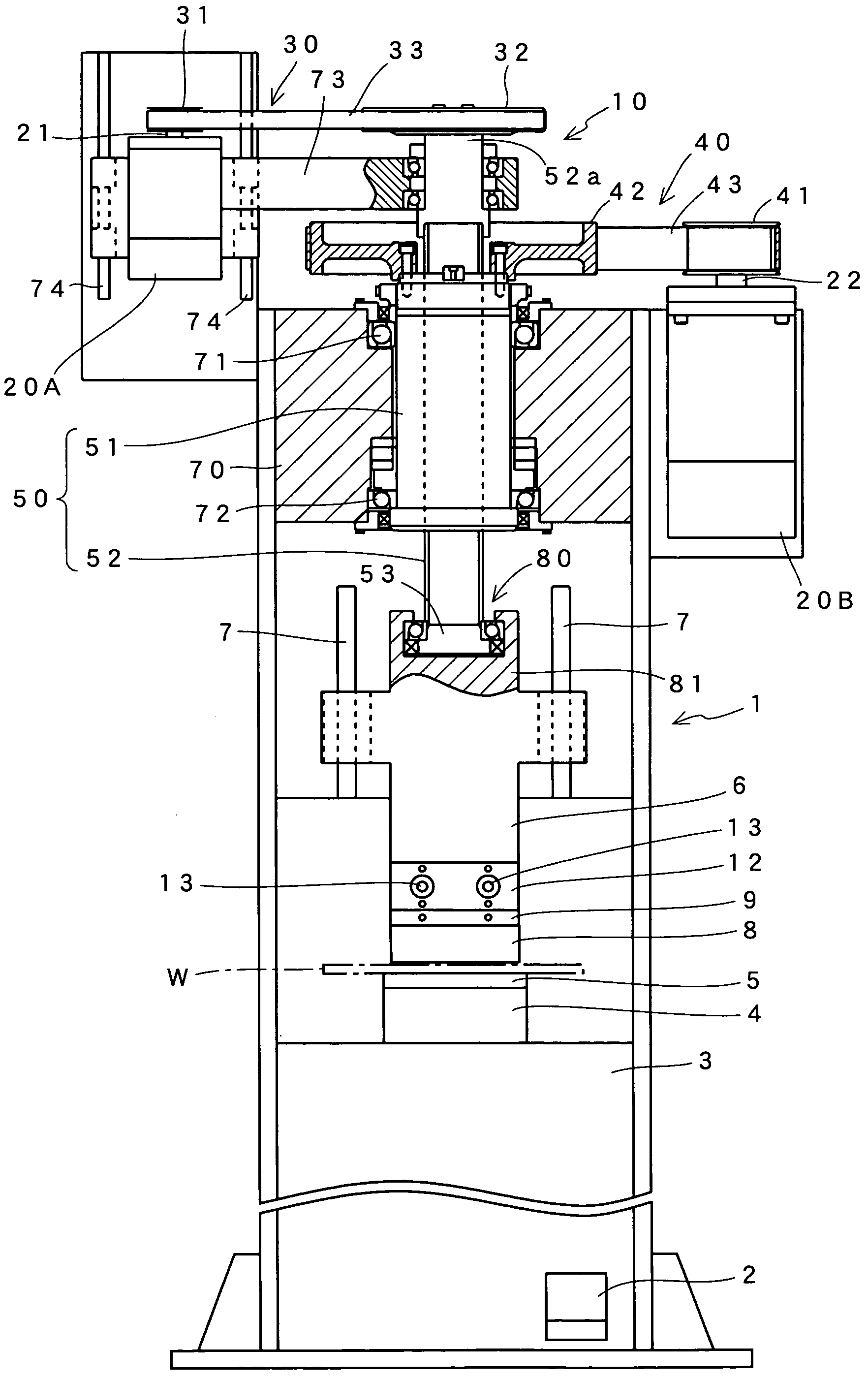
[0047]FIG. 1 shows the configuration of a press brake which is an embodiment of this invention. The press brake of the shown example comprises a machine body 1 which is installed on a floor, and an electric control box (not shown) which is provided with an operation unit for key entry, a display unit for data display, and so on. The machine body 1 is one in which a table 4 for supporting a lower die 5 is attached to the top surface of a bed 3. Above this table 4, a ram 6 is arranged so as to be capable of moving up and down along guides 7 on both sides.

[0048]An upper die 8 is attached to the bottom of the ram 6 via an adapter 12 and a holder 9. A plate-like work W supported on the lower die 5 is bent into a predetermined angle under the application of a pressing force from the upper die 8. The adapter 12 is intended to turn right and left eccentric shafts 13 to adjust the tilt of the upper die 8.

[0049]A foot switch 2 is arranged in the lower part of the bed 3. When an operator steps...


PUM

PropertyMeasurementUnit
speedaaaaaaaaaa
torqueaaaaaaaaaa
friction surfaceaaaaaaaaaa

Abstract

A reciprocating drive mechanism for converting motor rotation into linear motions to produce a reciprocating drive force, and a press machine using the mechanism. The rotation of a first motor (20A) out of two motors (20A) and (20B) is converted into a high-speed low-torque rotational output and transmitted to a ball screw mechanism (50) by a first power transmission mechanism (30). The rotation of the second motor (20B) is converted into a low-speed high-torque rotational output and transmitted to the ball screw mechanism (50) by a second power transmission mechanism (40). The ball screw mechanism (50) is made of a feed screw (52) supported in a screw hole of a nut member (51) so as to be capable of screw-fed rotation. The feed screw (52) and the nut member (51) are coupled with the first power transmission mechanism (30) and the second power transmission mechanism (40), respectively. A corotation prevention mechanism (80) prevents the feed screw (52) from rotating together with the rotation of the nut member (51).

Description

TECHNICAL FIELD[0001]This invention relates to a reciprocating drive mechanism for converting motor rotation into linear motions to produce a reciprocating drive force. In particular, this invention relates to a reciprocating drive mechanism for use in a press machine such as a press brake and an injection molding machine, and to a press machine using the reciprocating drive mechanism.BACKGROUND ART[0002]In conventional typical press brakes, as shown in FIG. 7, a lower die 101 and an upper die 103 are attached to the top surface of a table 100 and the bottom of a not-shown ram via a holder 102, respectively, so that they are opposed to each other. A plate-like work W is supported on the lower die 101. The upper die 103 is lowered toward this work W together with the ram. The upper die 103 comes into contact with the work W on the way down, and the work W undergoes a pressing force from the upper die 103. The work W is pushed into a V-shaped groove 104 of the lower die 101 by this pr...

Claims


Application Information

Patent Timeline
Patent Type & Authority Patents(United States)
IPC IPC(8): B21D9/05B21J7/46B21J9/18B30B1/18B21D5/02F16H25/20
CPCB30B1/18F16H25/2018B30B1/186F16H25/2204
Inventor IMAEDA, WATARU
Owner AMADA CO LTD
Why Eureka
Try Eureka