
Self-calibrating liquid level transmitter

a capacitance sensor and liquid level technology, applied in liquid/fluent solid measurement, instruments, machines/engines, etc., can solve the problems of inherently vulnerable capacitance sensors to fluid characteristics changes, and detection based on capacitance is also limited

Active Publication Date: 2007-10-23
LUMENITE CONTROL TECH
View PDF135 Cites 30 Cited by
  • Summary
  • Abstract
  • Description
  • Claims
  • Application Information

AI Technical Summary

Benefits of technology

[0009]In one embodiment of the present disclosure, the thickness of the insulation of a capacitance body is varied along a precise function along its vertical axis. The variations at determined levels creates a change in the variability measurement of the capacitance of the fluid leading to a recalibrating level for the capacitance sensor. In another embodiment of the present disclosure, the surface geometry of the capacitance body is varied along a precise function along its vertical axis. The variations at determined levels also create a change in the variability measurement of the capacitance of the fluid and can be used to recalibrating the level for a capacitance sensor measure. In another embodi

Problems solved by technology

Capacitance sensors are inherently vulnerable to changes in fluid characteristics since the dielectric constant of fluids may vary greatly with temperature, chemical composition, pollutants, segregation, phase changes, and other fluid characteristics.
Detection based on capacitance is also limited by nonintrusive size sensors with limited surface area and the need to measure at low voltage levels.

Method used


Image

  • Self-calibrating liquid level transmitter
  • Self-calibrating liquid level transmitter
  • Self-calibrating liquid level transmitter

Examples


second embodiment

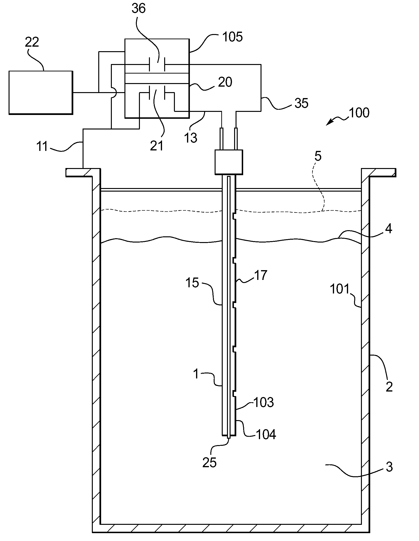
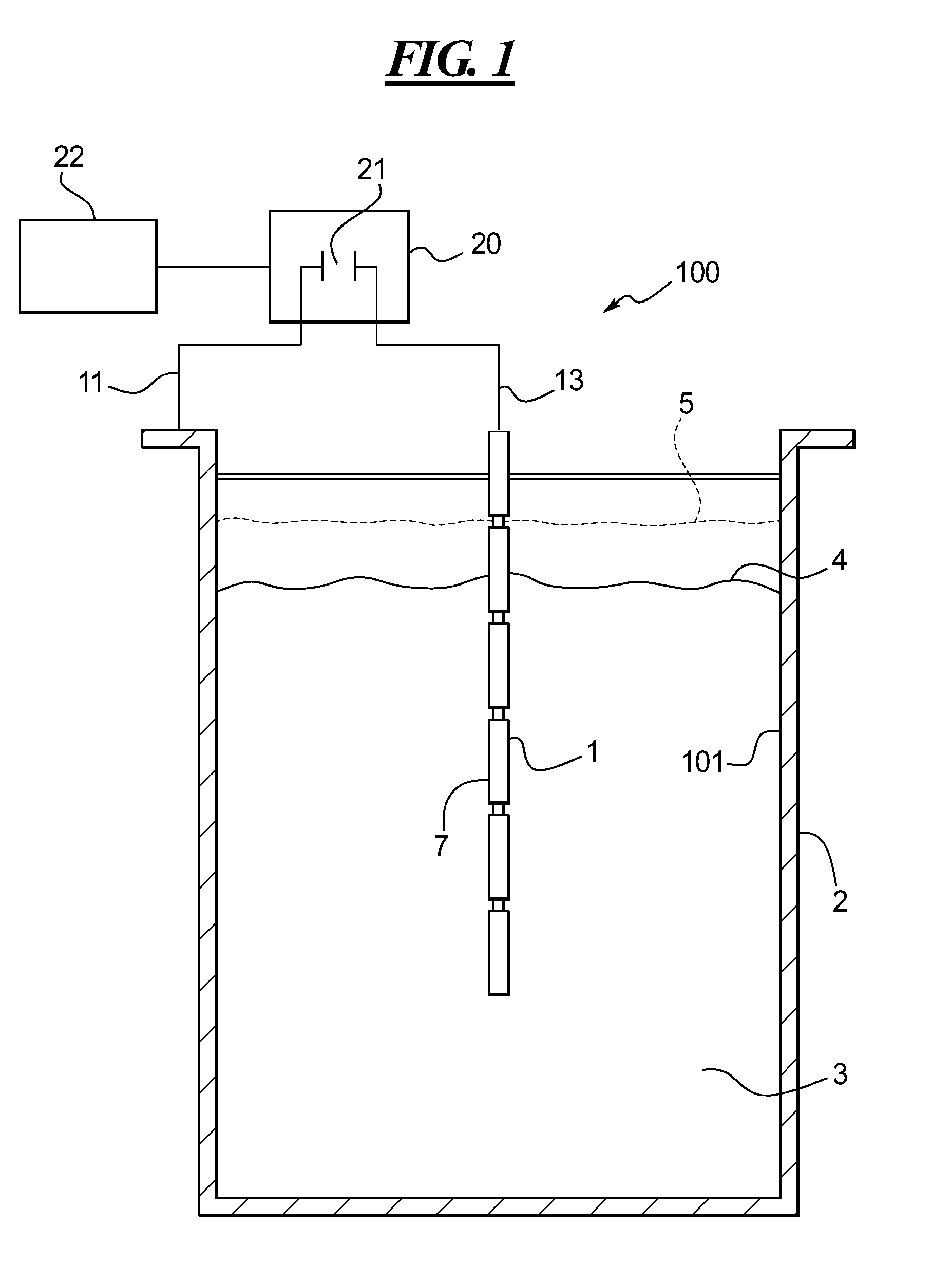
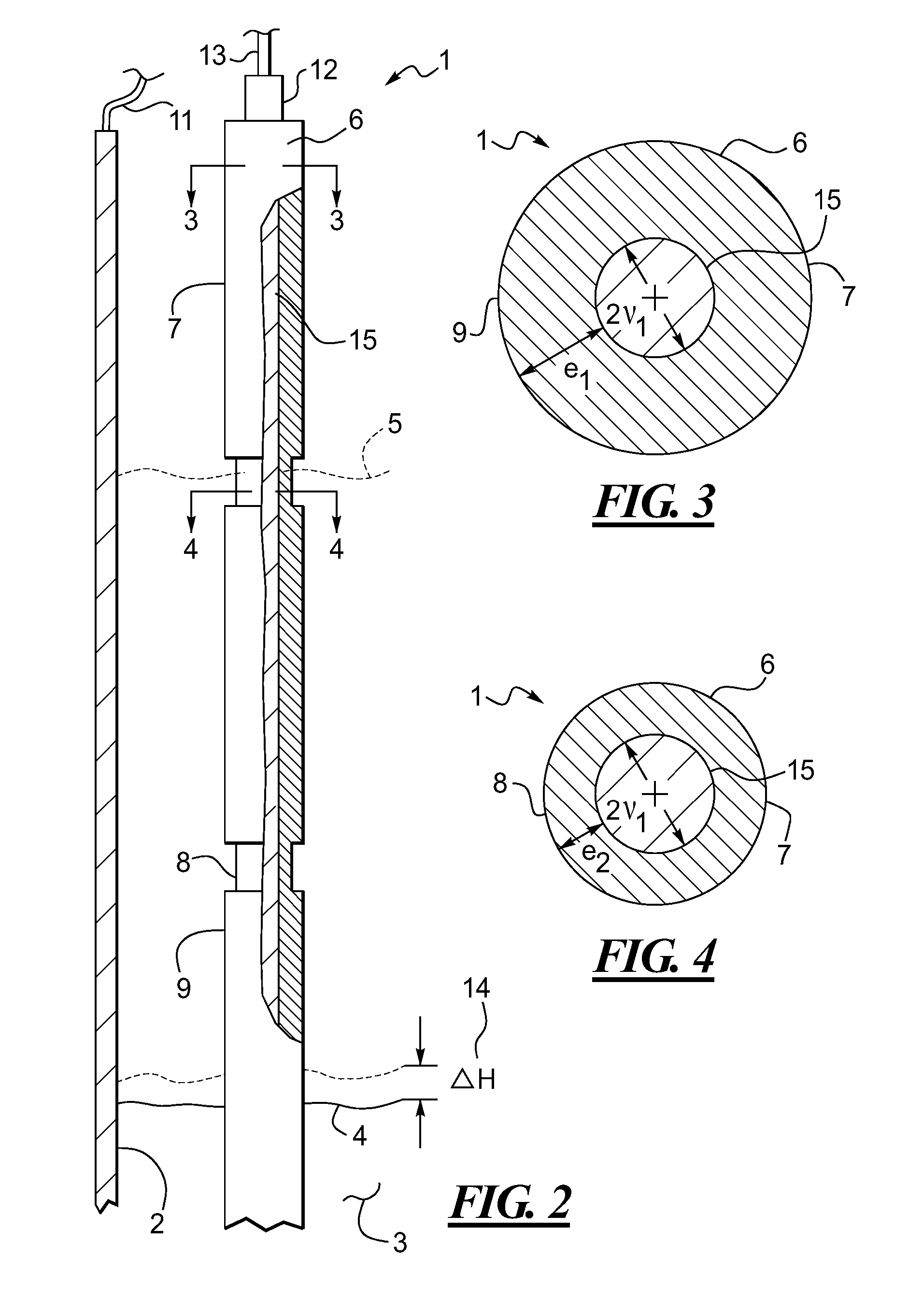
[0036]FIG. 1 is a functional side view of the self-calibrating capacitance fluid level sensing apparatus according to a first and second embodiment of the present disclosure. The first contemplated embodiment of the sensing apparatus to be placed in a container includes a sensor 100 with a first body 1 made of electrically conductive material, a layer of insulating material 7 as shown in FIG. 2 of a thickness e1 or e2 shown in FIGS. 3-4. The insulating material 7 is placed over the first body 1 covering a first surface contact area 15 shown in FIG. 2. The sensor 100 also comprises a second body 2 with a second surface contact area 101 made of electrically conductive material placed in opposition to the first body 15.

[0037]In one embodiment, the second body 2 is a container and the second surface contact area 101 is the inside portion of a stainless steel container, reservoir, or vat without surface insulation. It is understood by one of ordinary skill in the art that in order to cre...

fifth embodiment

[0055]Certain embodiments include in one embodiment thereof a circular vertical probe 40 made of stainless steel covered in the fifth embodiment by a layer of insulating Teflon®26. In one embodiment, the reed switches 47 are separated vertically by 4 inches and the container of the second contact surface 2 of the container is the inside wall of the container 101. In yet another embodiment, the fluid is water and the means for establishing a magnetic field is a ring magnet 45 located in the center of the floater 42. It is also contemplated that other means for establishing a magnetic field be used, such as a localized current, a magnet, or a magnetic element located on the surface of the water. In another embodiment, the floater 42 is made of a hollowed volume made of stainless steel. It is understood by one of ordinary skill in the art that while a stainless steel floater is shown, any type of floater in any noncorrosive material in contact with the fluid 3 is contemplated.

first embodiment

[0056]FIG. 19 discloses a first method for measuring the fluid level in a container with a self-calibrating sensing apparatus in accordance with one embodiment of the present disclosure. The self-calibration is obtained by conducting a first step where the capacitance sensor of the first embodiment is placed in the container where a lower measure point is in contact with a low level of a fluid to be measured and the higher measure point is in contact with a high level of the fluid to be measured 201, a calibration of the capacitance sensor to the desired output range is then performed so the lower measure point is a first extremity of the output range and the high measure point is a second extremity of the output range 202. The capacitance sensor and means for detecting the variability of the voltage using a determination method to recognize variations associated with the successive levels in the step function associated with the changes in thickness of the insulation are then calib...


PUM


Abstract

The present disclosure generally relates to a capacitance sensing apparatus equipped with self-calibrating capacity and method of use thereof. The disclosure contemplates the determination using a secondary means of precise fluid levels according to five possible embodiments, and the use of the determined fluid level to recalibrate the capacitance sensing apparatus along its continuous analog level, namely, a variation of the thickness of the insulation of a capacitance sensing apparatus, the variation of the surface geometry of the capacitance sensing apparatus, the use of a dual-probe sensor including a probe with a varied surface geometry, the use of an electromagnetic sensor adjoining the capacitance sensor, and the variation of the electromechanical sensor to serve as a capacitance sensing apparatus. The disclosure also contemplates methods for using the sensing apparatus previously disclosed to measure a fluid level using a self-calibrating capacitance sensing apparatus. Finally, the present disclosure contemplates the use of an improved mathematical method associated with a variability measurement, such as an exponential smoothing method, to determining locally discrete changes in the variability measurement of the capacitance in order to determine a fixed fluid level.

Description

RELATED APPLICATIONS[0001]This application claims the benefit of U.S. Provisional Application No. 60 / 595,135, filed on Jun. 8, 2005.FIELD OF THE DISCLOSURE[0002]This disclosure relates to a self-calibrating capacitance fluid level sensing apparatus and method of use thereof, and more particularly, to an analog capacitance fluid level sensing apparatus further calibrated at fixed fluid levels with a signal from either a variable thickness in the insulated capacitance probe, a variable geometry of the capacitance probe, an input from an adjoining electromechanical sensor, or an input from a joined electromechanical sensor.BACKGROUND[0003]Varied technologies exist to measure fluid levels in containers. These technologies include but are not limited to mechanical sensors, electromechanical sensors, radar sensors, visual sensors, weight sensors, laser sensors, ultrasonic sensors, and capacitance sensors. Fluid characteristics such temperature, viscosity, conductivity, chemical abrasivene...

Claims


Application Information

Patent Timeline
IPC IPC(8): G01F23/00
CPCG01F23/268G01F23/266
Inventor CALABRESE, RONALD V.
Owner LUMENITE CONTROL TECH
Learn More