Systems and methods for aerial dispersion of materials

a material and material technology, applied in the field of aircraft systems, can solve the problems of lack of fire-fighting aircraft, limited maffs capacity, loss of aircraft and crew, etc., and achieve the effect of high lift capacity

Inactive Publication Date: 2007-10-23
L 3 INTEGRATED SYST +1
View PDF26 Cites 22 Cited by
  • Summary
  • Abstract
  • Description
  • Claims
  • Application Information

AI Technical Summary

Benefits of technology

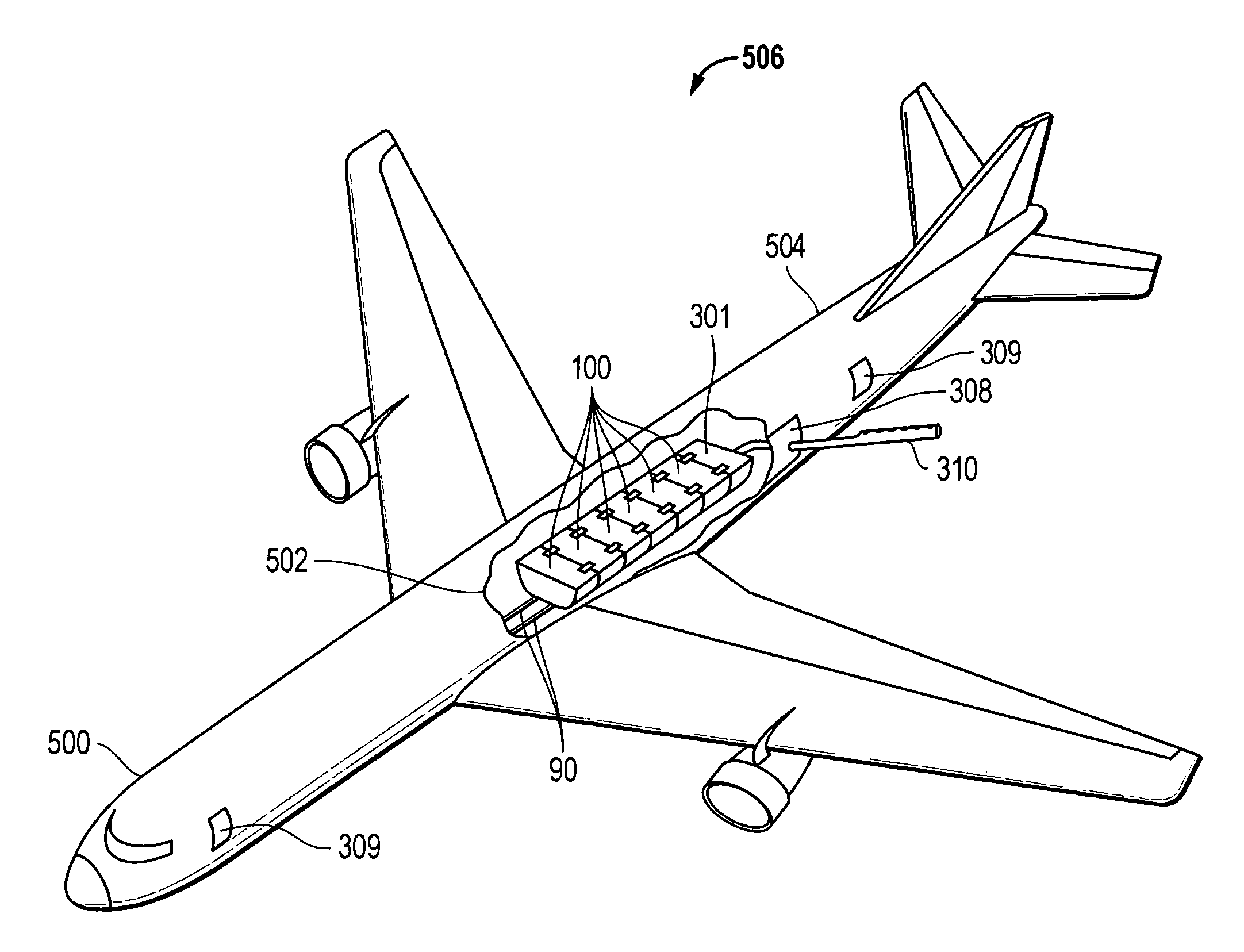
[0008]Disclosed are methods and systems that may be implemented to allow rapid and temporary conversion of aircraft for aerial dispersion purposes, such as aerial fire-fighting. The aerial dispersion equipment of the disclosed systems and methods may be implemented using modular components that may be configured for compatibility with conventional cargo loading and unloading systems of modern aircraft, including side-loading cargo systems of wide body passenger and cargo aircraft having high lift capacities. In one embodiment, wide body commercial aircraft may be quickly and temporarily modified for aerial dispersion purposes, allowing a large fleet of high capacity aerial dispersion aircraft to be quickly assembled, for example, in response to a wildfire or other rapidly-developing emergency such as an oil spill, chemical or biological contamination incident, building or refinery fire, etc. After use, the aircraft may be rapidly de-modified and returned to original condition, e.g., as commercial passenger or cargo plane, or as military transport or bomber. In another embodiment, such a fleet of aerial dispersion aircraft may be configured to operate in a coordinated manner, for example, as part of an aerial firefighting formation sharing common control such as ground control or lead aircraft that directs flight path and / or release of materials from individual aircraft in the formation. Military heavy lift aircraft (e.g., including transport and bomber aircraft) may be similarly converted and employed, either in combination with or as an alternative to commercial aircraft.
[0009]The disclosed systems and methods may be configured to utilize relatively inexpensive modular equipment that may be quickly loaded onto and unloaded from an aircraft using the conventional cargo systems of the aircraft, advantageously allowing modification and de-modification of side-loading aircraft that do not have a wide rear cargo ramp such as possessed by C-130 aircraft. For example, modular and connectable units in the shape of conventional cargo pods may be rapidly loaded and unloaded through side cargo doors into the cargo hold of high lift capacity wide body commercial aircraft (e.g., such as 747, 767, 777 or MD-11 aircraft) or high lift capacity wide body military / cargo aircraft (e.g., such as C-5, C-141, etc.) in a manner consistent with normal cargo loading operations to provide a removable and re-useable aerial dispersion system having a capacity much larger than the capacity of existing aerial dispersion systems. In those embodiments where the modular units are configured in the shape of conventional cargo pods, they may be employed with a wide variety of aircraft types that employ the same type of cargo pods regardless of the capacity of a given aircraft. Furthermore, the modular nature of the cargo pods allows a given aircraft to be provided with an aerial dispersion system of desired or customized capacity and / or capability to fit a given application, i.e., by loading a desired number and type of modular units required to provide the desired capacity and capabilities of the system.
[0010]The high capacity aerial dispersion systems that may be provided using the disclosed systems and methods make possible aerial dispersion techniques that do not require low altitude or high angle dives or climbs to apply aerial dispersants to targets, such as fire hot spots. In this regard, high lift capacity wide-body aircraft may be provided with aerial dispersion systems having a capacity of aerial dispersant material that is many times the capacity of existing aerial dispersion systems. Using these high capacity aerial dispersion systems allows high volumes of aerial dispersant to be effectively applied to a target drop point location from a higher altitude without requiring steep diving or climbing maneuvers that may result in unacceptable g-force stresses. Furthermore, since the disclosed aerial dispersion systems may be rapidly installed on conventional commercial and / or military aircraft, it is possible to provide a large number of high capacity aerial dispersion aircraft that may be deployed together to provide a very large volume of aerial dispersant simultaneously and / or sequentially onto a given target or targets, e.g., to rapidly and effectively suppress a wildfire. Following the aerial dispersion mission, the disclosed aerial dispersion systems my be rapidly de-installed or removed from the aircraft so that the commercial or military aircraft may be quickly returned to normal configuration for resumption of conventional flight operations.

Problems solved by technology

The nature of these low altitude bombing runs often result in g-force stresses that exceed the structural rating of these aircraft, weakening the structure of the aircraft and in some cases causing in-flight structural failures leading to loss of the aircraft and crew.
A limited supply of vintage aircraft and the grounding of particular types of aircraft due to structural weaknesses has resulted in a shortage of fire-fighting aircraft.
In addition to limitations in MAFFS capacity and drop pattern, certain C-130 aircraft that are employed for MAFFS purposes have been recently grounded due to excessive stresses imparted on these aircraft when using them for aerial fire-fighting.
However, the CL-415 is very expensive relative to vintage aircraft, has a limited carrying capacity of approximately 1621 gallons of liquid fire retardant material, and the cost of obtaining and maintaining a state-of-the-art modern fleet of such aircraft would be prohibitive.
Thus, the relatively small carrying capacity, specialized nature, and high cost of such aircraft prohibits large-scale deployment in an aerial fire-fighting fleet.

Method used


Image

  • Systems and methods for aerial dispersion of materials
  • Systems and methods for aerial dispersion of materials
  • Systems and methods for aerial dispersion of materials

Examples


Embodiment Construction

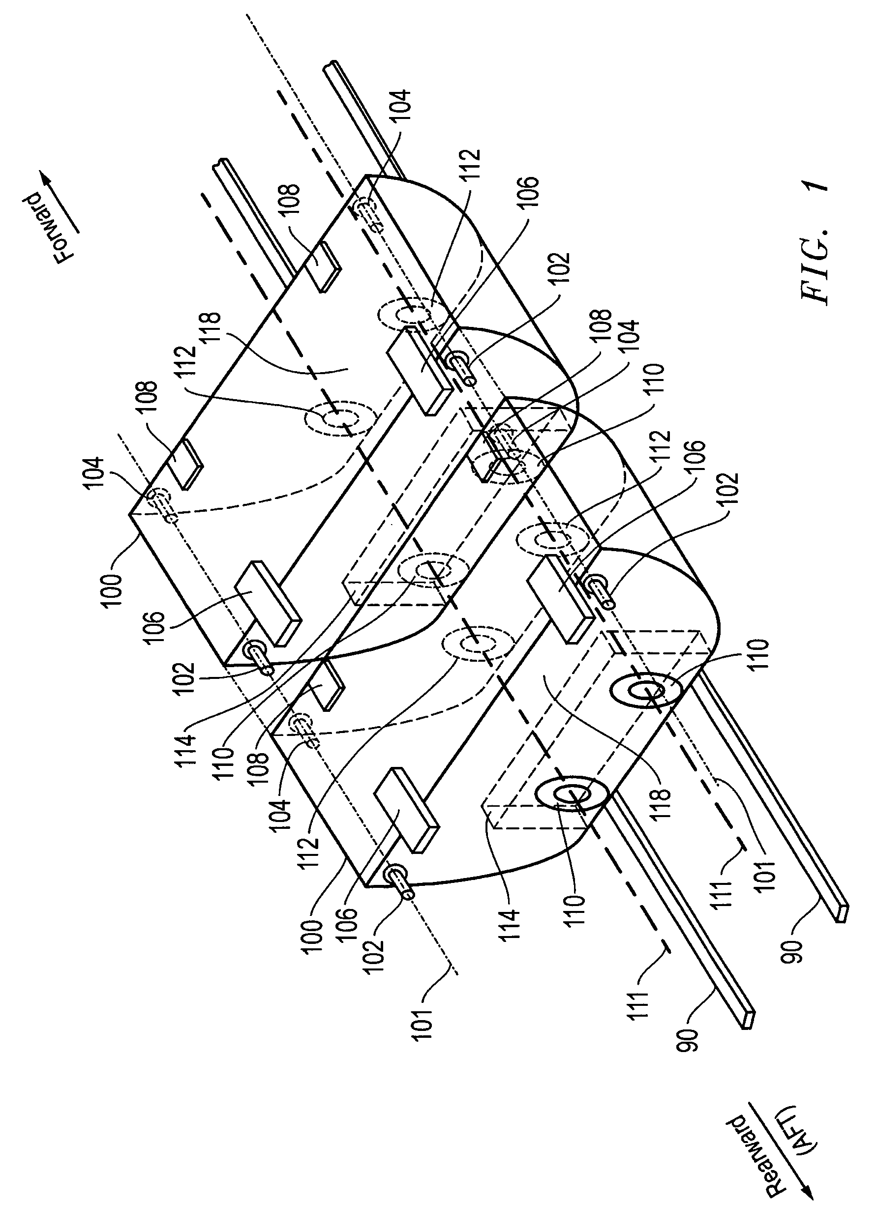
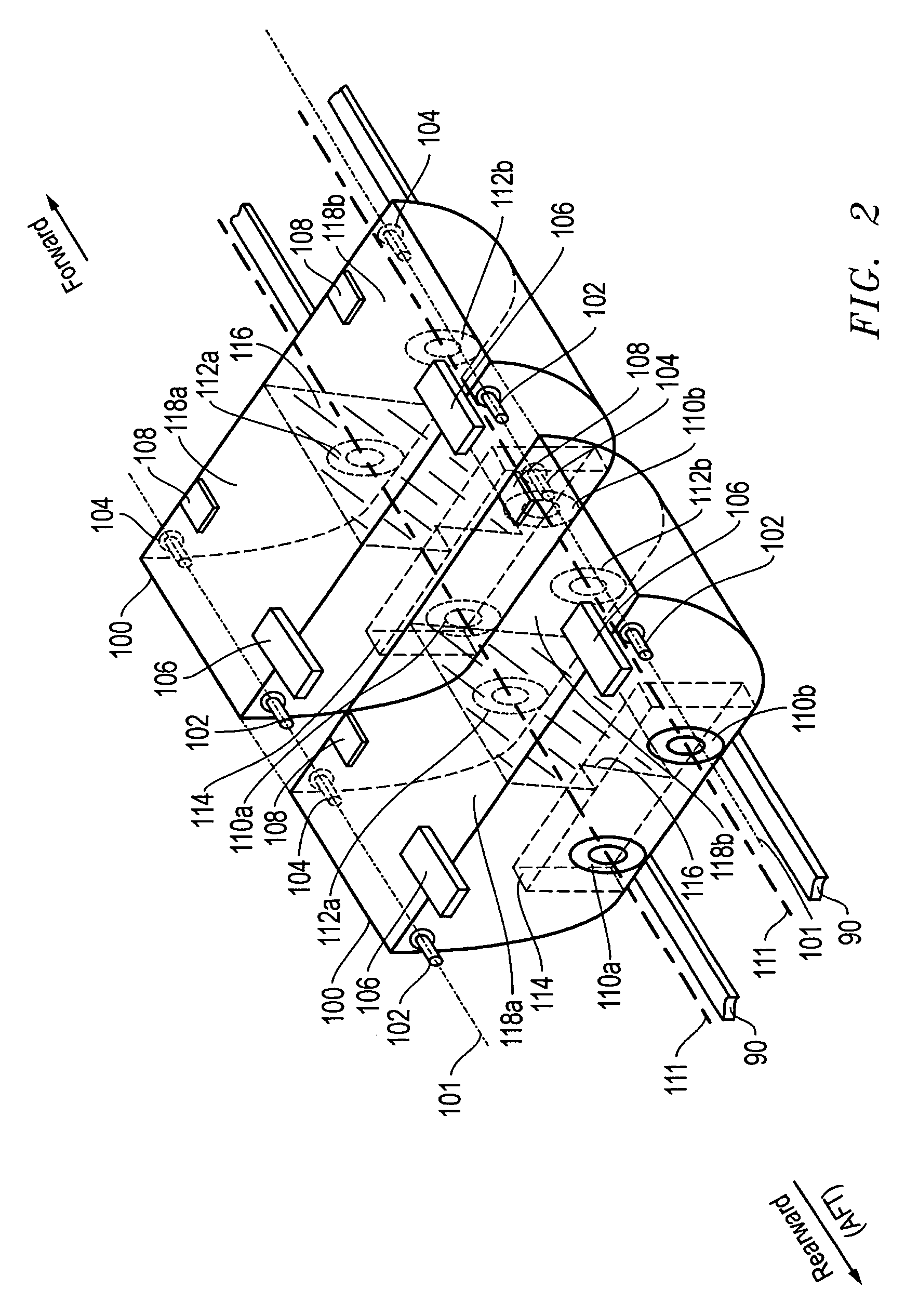
[0022]FIG. 1 illustrates aerial dispersant holding tanks 100 that may be employed in one embodiment to temporarily modify an aircraft, such commercial or military wide-body aircraft, for the aerial dispersement of materials. FIG. 1 shows two aerial dispersant holding tanks 100 positioned in a front end-to-rear end relationship as they may be deployed within the baggage or cargo hold of an aircraft. However, it will be understood that any number of such tanks 100 may be flexibly employed in a given aircraft as may be desirable or required to fit the needs of a given application. In this regard, a greater number of tanks 100 may be employed in aircraft having longer cargo holds and higher lift capacities, and / or in those situations where it is desirable to provide a relatively large volume for carrying dispersant material. A smaller number of tanks 100 may be employed in smaller aircraft and / or in situations where it is desirable to provide a relatively smaller volume for carrying dis...


PUM


Abstract

Aerial dispersion systems that may be employed to allow rapid and temporary conversion of aircraft for aerial dispersion purposes, such as aerial fire-fighting. The aerial dispersion systems may be implemented using modular components that may be configured for compatibility with conventional cargo loading and unloading systems of modern aircraft, including side-loading cargo systems of wide body passenger and cargo aircraft having high lift capacities. The aerial dispersion systems may be rapidly installed in a large fleet of high capacity aircraft in response to a wildfire or other rapidly-developing emergency such as an oil spill, chemical or biological contamination incident, building or refinery fire, etc. After use, the aircraft of the fleet may be rapidly de-modified and returned to original condition. The aerial dispersion systems may be operated with a fleet of aircraft in a coordinated manner, for example, as part of an aerial firefighting formation having multiple aircraft sharing information and / or common control.

Description

BACKGROUND OF THE INVENTION[0001]1. Field of the Invention[0002]This invention relates generally to aircraft systems, and more particularly to aircraft systems that may be used for aerial dispersion of materials.[0003]2. Description of the Related Art[0004]Aircraft are commonly employed for the aerial dispersion of liquid and / or solid materials such as fire retardant or fire extinguishing materials, oil dispersant materials, bio-remediation materials, fertilizer materials, herbicide materials, defoliant materials, pesticide materials, etc. For example, specially-equipped aircraft are used to carry and deliver fire retardant materials to the area of a forest or brush fire. Such fire-fighting aircraft are typically converted World War II era bombers or propeller-driven passenger or cargo planes that have a carrying capacity limited to 3000 gallons or less of liquid fire retardant material. These vintage aircraft typically deliver their load of fire retardant material by flying to the ...

Claims


Application Information

Patent Timeline
Patent Type & Authority Patents(United States)
IPC IPC(8): B64D1/18B64D9/00A62C3/02B64D1/16
CPCB64D1/16A62C3/0242
Inventor NOLAN, BROOKS R.
Owner L 3 INTEGRATED SYST
Why Eureka
Try Eureka