Distributed optical fibre measurements

a technology of optical fibres and optical fibers, applied in the direction of optical radiation measurement, heat measurement, instruments, etc., can solve problems such as unwanted nonlinear effects, and achieve the effects of improving measurement accuracy, close alignment loss characteristics, and enhancing managemen

Inactive Publication Date: 2007-10-23
SCHLUMBERGER TECH CORP
View PDF5 Cites 80 Cited by
  • Summary
  • Abstract
  • Description
  • Claims
  • Application Information

AI Technical Summary

Benefits of technology

[0016]The measurement and use of a fourth, low power, output signal corresponding to elastic (Rayleigh) scattering of light at the first wavelength allows any nonlinear distortion of the first and second output signals to be compensated for, so that it does not distort the measurement. The second output signal, representing Rayleigh scattering at the first wavelength, may typically be obtained at a relatively high power level. This can lead to unwanted nonlinear effects, in particular stimulated Raman scattering, that convert power away from the first wavelength. Obtaining two Rayleigh scattering signals at the first wavelength, one at low power and one at high power, enables the effect of any nonlinearity to be discounted, because the low power signal should be free from any nonlinear distortion. Thus the accuracy of the measurement is improved.
[0028]Preferably, the one or more optical sources comprises a single optical source operable to generate the first optical signal and the third optical signal, the single optical source comprising a power control operable to alter the optical power level of an optical signal generated by the single optical source between the first optical power level and the second optical power level. This provides a simpler apparatus with fewer components.

Problems solved by technology

This can lead to unwanted nonlinear effects, in particular stimulated Raman scattering, that convert power away from the first wavelength.

Method used


Image

  • Distributed optical fibre measurements
  • Distributed optical fibre measurements
  • Distributed optical fibre measurements

Examples


first embodiment

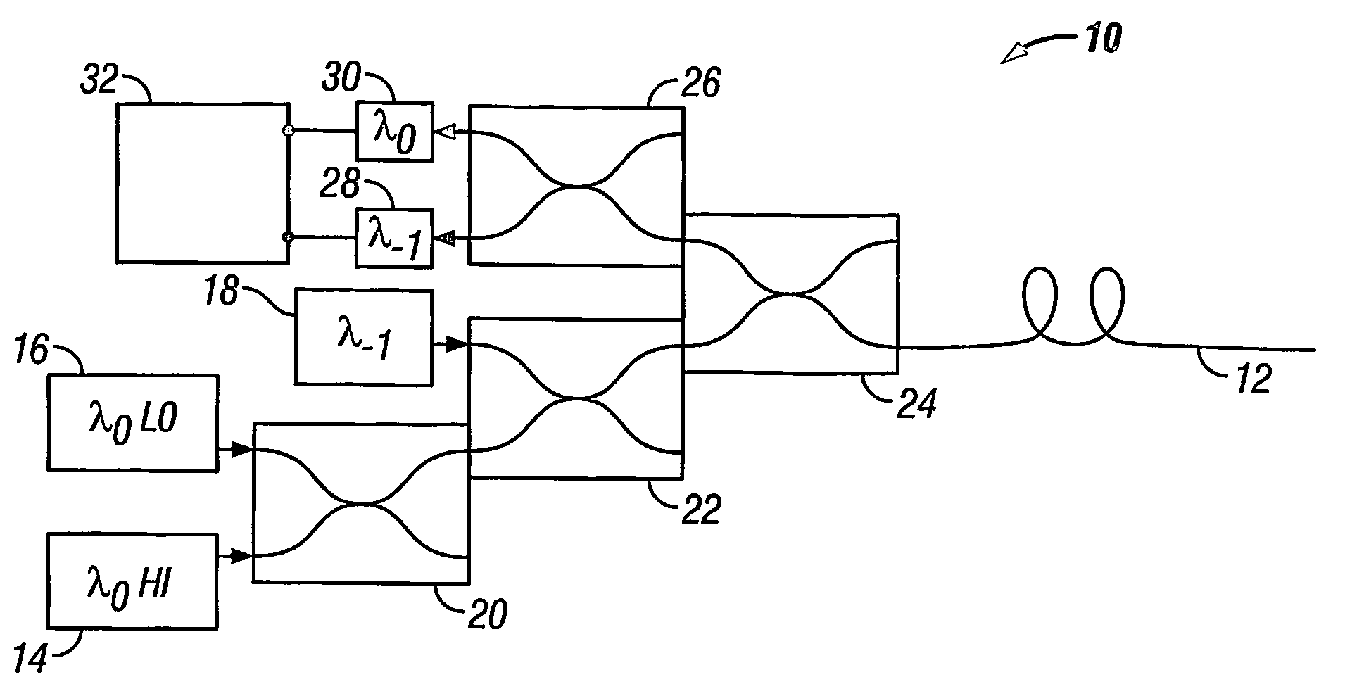
[0093]Apparatus may be configured in a number of ways to implement the present invention.

[0094]FIG. 1 shows a schematic representation of a first example of apparatus suitable for implementing the method of the present invention.

[0095]The apparatus 10 comprises a length of optical fibre 12 arranged to be deployed in a measurement region of interest, having an associated parameter of interest of a kind that affects the optical propagation characteristics of the fibre 12. The length of the optical fibre 12 is such that it extends at least over a distance within the measurement region which is of interest. The fibre 12 is arranged for single-ended operation, in that all associated equipment is positioned at one end of the fibre 12. This is advantageous because measurements can be made in environments and circumstances in which it is not possible or practical to access both ends of the fibre 12.

[0096]As discussed above in the theory section, measurements are made using a combination of ...

second embodiment

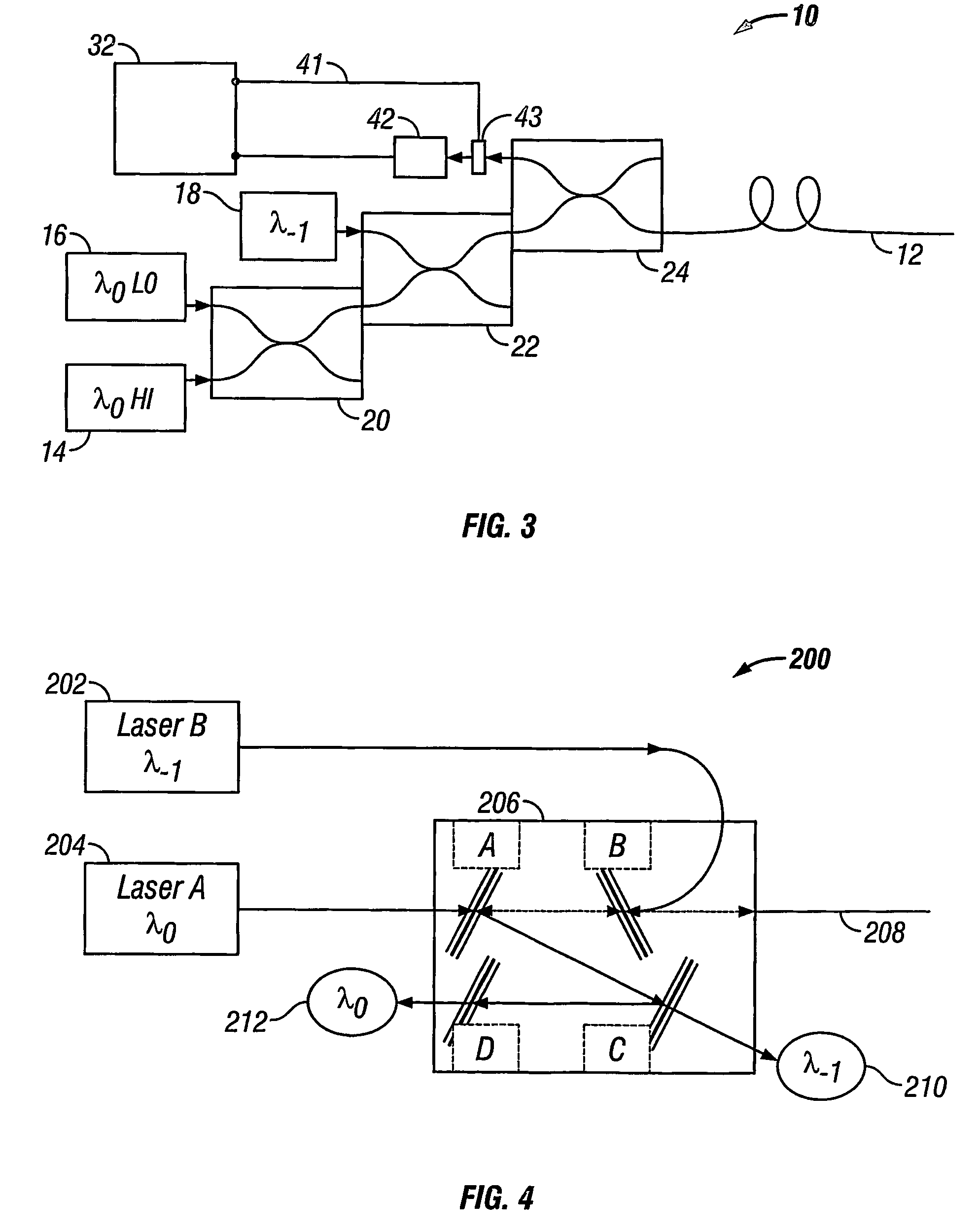
[0111]The examples and embodiments presented thus far have used fused fibre couplers to direct the various light signals between the optical sources, the sensing fibre and the detectors. Couplers of this kind are particularly applicable to systems using single mode optical fibre, for which single mode fused couplers with the necessary wavelength-dependent power splitting and coupling capability are readily available. However, in the event that multimode optical fibre is used for the sensing fibre, an alternative approach may be adopted. Fused tapered fibre couplers are available for multimode fibre, but these devices tend to lack the required wavelength-dependent operation. Therefore, a multimode system may instead comprise bulk optic coupling and splitting arrangements to achieve the same result.

[0112]FIG. 4 shows a schematic diagram of such a system. The apparatus 200 comprises a first optical source 202 operable to generate light at wavelength λ−1 to form the second optical signa...
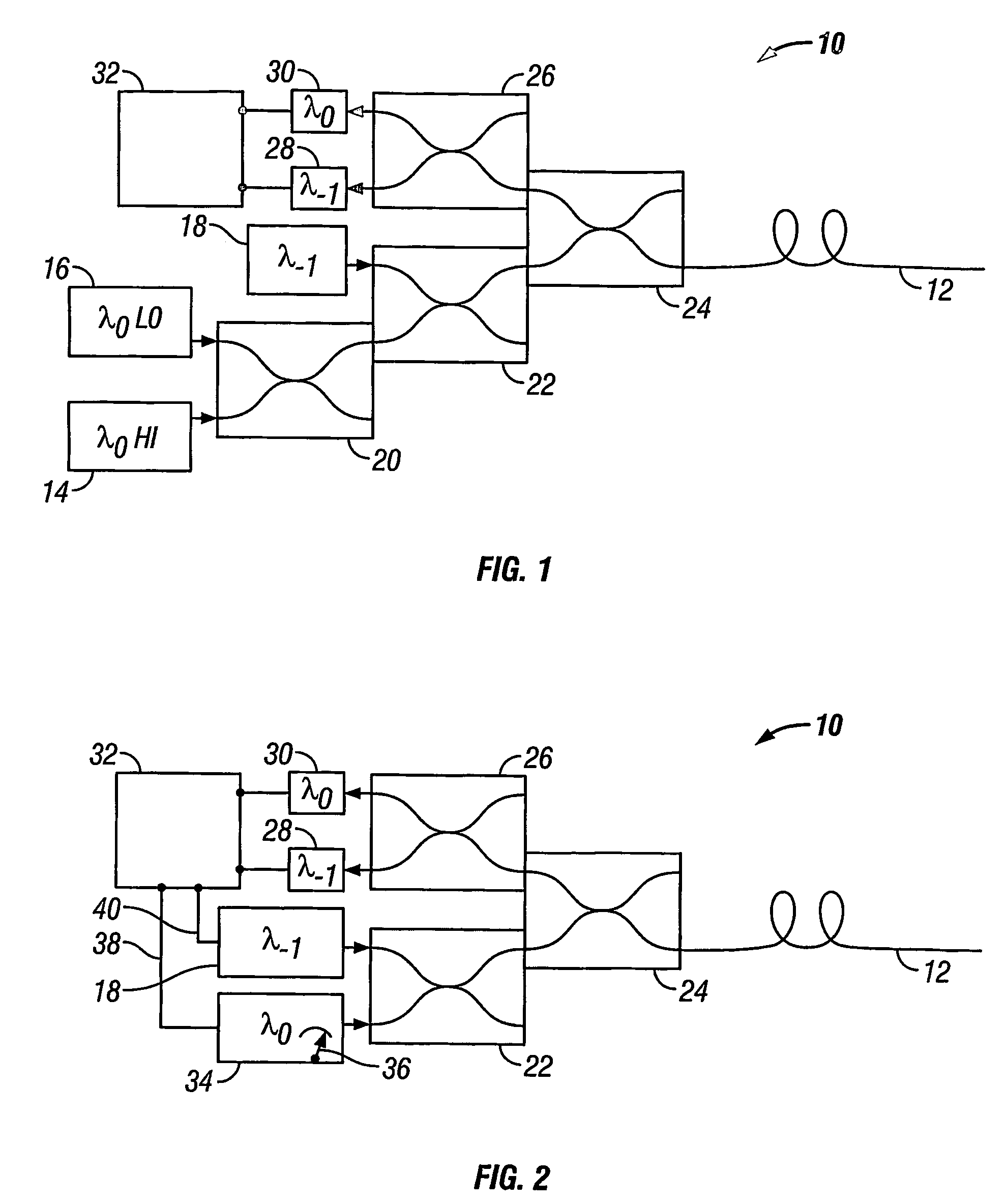
third embodiment

[0124]The purpose of the third output signal, being the Rayleigh signal at λ−1, is to normalise the losses suffered by the first output signal, which is the Raman signal at λ−1. However, these two signals originate from different sources, namely the Raman scattering event in the case of the first output signal, and the second optical source 18 in the case of the third output signal. The spectrum of the Raman scattering is typically broad, so that it may exceed the spectral bandwidth of the second optical source 18. In some cases the Raman spectrum may exceed that of any available optical source operating at the appropriate wavelength. The attenuation seen by the two signals is therefore likely to be different.

[0125]Therefore, to improve the accuracy of the normalisation, according to a third embodiment of the invention, the spectrum of the second optical source 18 is matched to the Raman spectrum. A spectral modifier may be provided to achieve this, which may be implemented in sever...


PUM

PropertyMeasurementUnit
core diameteraaaaaaaaaa
first wavelength λ0aaaaaaaaaa

Abstract

A method of obtaining a distributed measurement comprises deploying an optical fibre in a measurement region of interest, and launching into it a first optical signal at a first wavelength λ0 and a high power level, a second optical signal at a second wavelength λ−1, and a third optical signal at the first wavelength λ0 and a low power level. These optical signals generate backscattered light at the second wavelength λ−1 arising from Raman scattering of the first optical signal which is indicative of a parameter to be measured, at the first wavelength λ0 arising from Rayleigh scattering of the first optical signal, at the second wavelength λ—1 arising from Rayleigh scattering of the second optical signal, and at the first wavelength λ0 arising from Rayleigh scattering of the third optical signal. The backscattered light is detected to generate four output signals, and a final output signal is derived by normalising the Raman scattering signal to a function derived from the three Rayleigh scattering signals, which removes the effects of wavelength-dependent and nonlinear loss.

Description

BACKGROUND OF THE INVENTION[0001]The present invention relates to methods of obtaining distributed measurements using optical fibres, and apparatus therefor.[0002]Techniques for using optical fibres to obtain distributed measurements of various parameters, such as optical time domain reflectometry and distributed temperature sensing, are well known. The underlying principle of these techniques is that light is injected into an end of the fibre, and undergoes scattering at all points along the length of the fibre. The amount and / or wavelength of the scattered light is affected by various parameters, such as temperature. Some of this light is backscattered to the fibre end, and the time at which it arrives at the fibre end is related to the position along the fibre at which it was scattered, owing to the constant speed of light within the fibre. Thus, detection of the backscattered light over time gives a representative profile of the parameter of interest over the length of the fibre...

Claims


Application Information

Patent Timeline
Patent Type & Authority Patents(United States)
IPC IPC(8): G01J5/00G01N21/00G01K11/32
CPCG01K11/32
Inventor HARTOG, ARTHUR H.
Owner SCHLUMBERGER TECH CORP
Why Eureka
Try Eureka