Downshift control for automotive automatic transmission

a technology of automatic transmission and downshift control, which is applied in the direction of electric control, ignition automatic control, machines/engines, etc., can solve the problems of large-scale shift shock, instantaneous increase in engine braking, and time required for downshift to be increased, so as to eliminate or reduce the effect of downshift shock

Active Publication Date: 2007-10-23
DENSO CORP
View PDF9 Cites 15 Cited by
  • Summary
  • Abstract
  • Description
  • Claims
  • Application Information

AI Technical Summary

Benefits of technology

[0012]It is another object of the invention to provide an improved structure of an automatic transmission controller designed to eliminate or alleviate a problem, such as unwanted acceleration of a vehicle during control of a downshift in the transmission executed in response to a request from a driver of the vehicle, which arises from, for example, a failure in operation of a hydraulic pressure control device.
[0013]According to one aspect of the invention, there is provided an automatic transmission control apparatus which may be employed in automotive vehicles. The automatic transmission control apparatus comprises: (a) a hydraulic control circuit which controls hydraulic pressures to be applied to a plurality of frictional elements such as clutches and brakes of an automatic transmission joined to an engine to selectively achieve engagement and disengagement of the frictional elements for establishing a required speed of the automatic transmission; (b) a defect detector working to detect a defect of the hydraulic control circuit; (c) an engine output increasing circuit designed to perform engine output increasing control to increase an output of the engine upon a downshift of the automatic transmission to develop engine braking in response to a request from an operator to decelerate a speed of the automatic transmission, the engine output increasing circuit initiating the engine output increasing control within an interval between start to control the hydraulic pressures through the hydraulic control circuit to achieve the downshift and start of an actual shift in speed of the automatic transmission; and (d) a fail-safe circuit working to stop the engine output increasing control immediately when the defect detector detects the defect of the hydraulic control circuit after the hydraulic control circuit starts to control the hydraulic pressures to achieve the downshift of the automatic transmission. This alleviates a problem such as unwanted acceleration of a vehicle during hydraulic control of a downshift in the transmission executed in response to a request from a driver of the vehicle.

Problems solved by technology

This may cause the time required for the downshift to be increased, thus giving rise to a delay in the engine braking or inertia torque arising from the increased speed of the engine to appear as braking torque, which results in an instantaneous increase in the engine braking, leading to a large-scale shift shock.
A rapid rise in torque transmitted through the frictional elements of the automatic transmission under hydraulic control will result in a quick rise in speed of the engine, so that the downshifting time decreases, but however, the braking torque increases excessively, thus resulting in a more increase in the shift shock.
Therefore, if a defect occurs in a hydraulic controller working to control the torque transfer capacity, it will result in an error in dropping the hydraulic pressure acting on the off-going frictional element and a difficulty in achieving the downshift.
For instance, in a case of a 4-3 downshift, the power of the engine is increased while a 4th speed gear ratio is locked without developing the engine braking, thus resulting in undesirable acceleration of the vehicle during the hydraulic control for the downshift.

Method used


Image

  • Downshift control for automotive automatic transmission
  • Downshift control for automotive automatic transmission
  • Downshift control for automotive automatic transmission

Examples


first embodiment

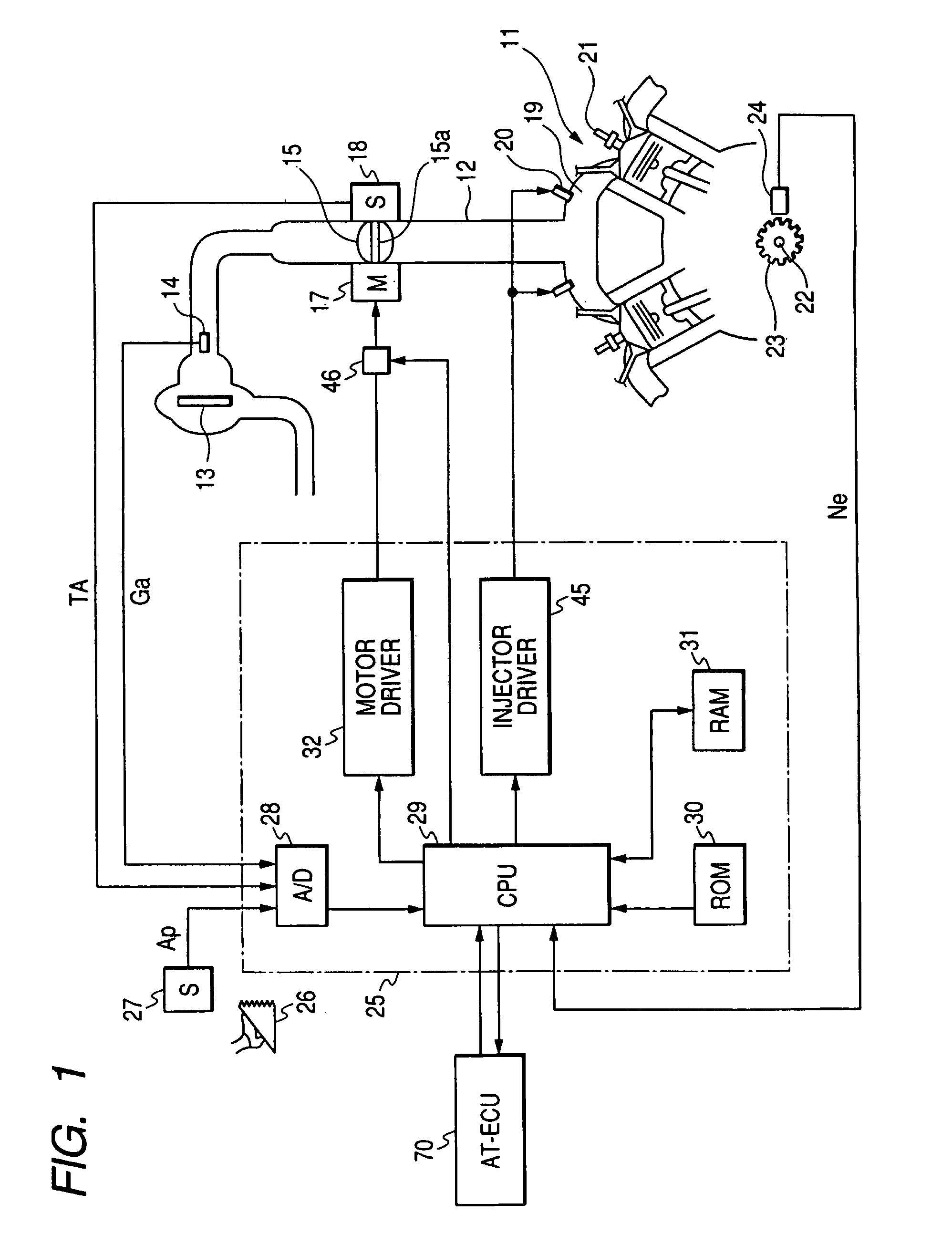
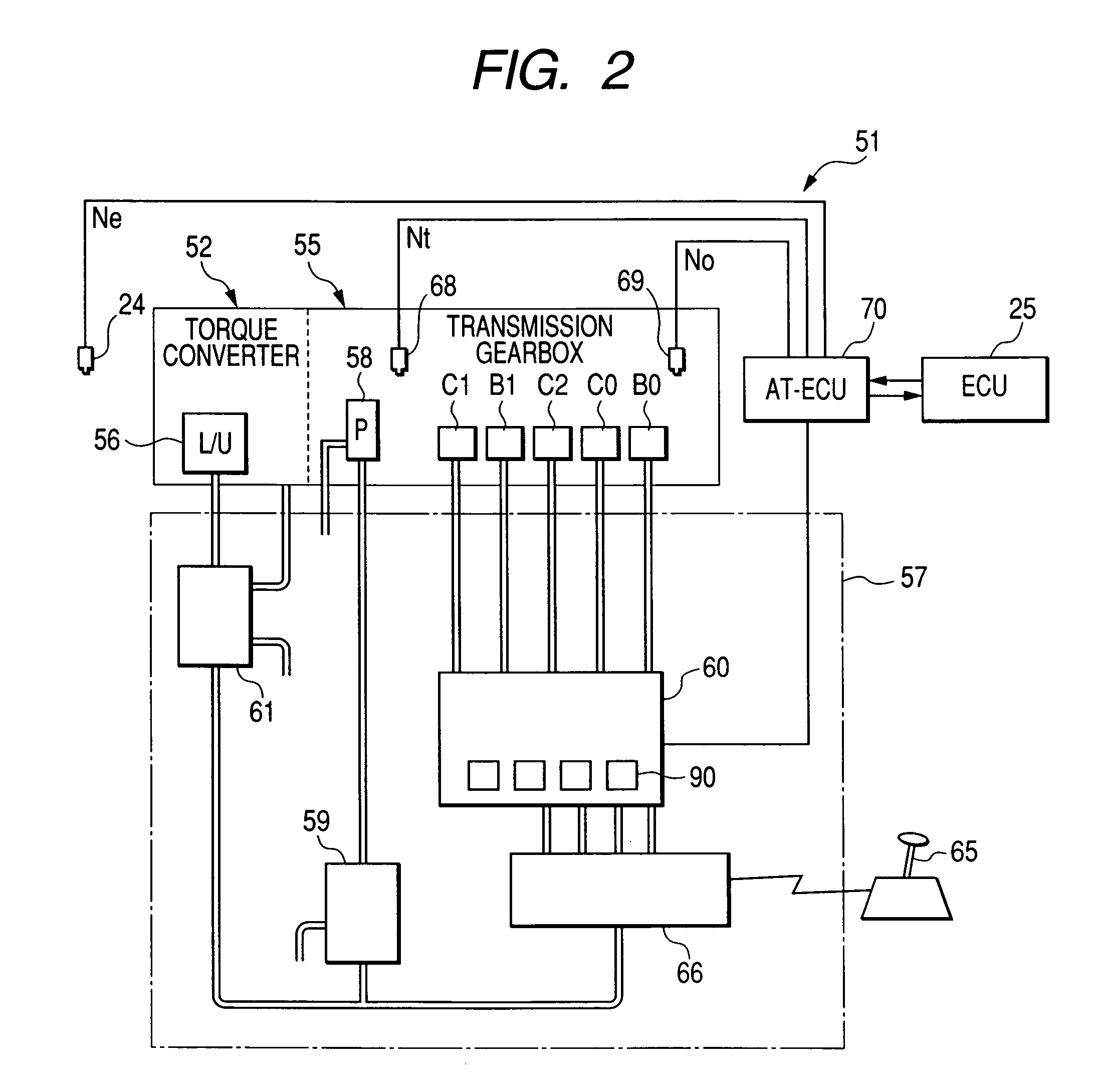
[0084]Referring to the drawings, wherein like reference numbers refer to like parts in several views, particularly to FIG. 1, there is shown an engine control system according to the invention which is designed to control an operation of an automotive internal combustion engine 11 and a downshift operation of an automatic transmission 51, as illustrated in FIG. 2, with aid of activity of an electronic throttle control (ETC) system.

[0085]The engine 11 is connected to an intake pipe 12. An air cleaner 13 is installed upstream of the intake pipe 12. An air flow meter 14 is disposed downstream of the air cleaner 13 which measures an intake air flow rate Ga. A throttle valve 15 is disposed downstream of the air flow meter 14. The throttle valve 15 has a rotating shaft 15a connected to an electric motor 17 such as a DC motor. The motor 17 works to control the position (i.e., the amount of throttle opening) of the throttle valve 15. A throttle position sensor 18 measures the position of th...

second embodiment

[0217]The engine control system of the second embodiment will be described below.

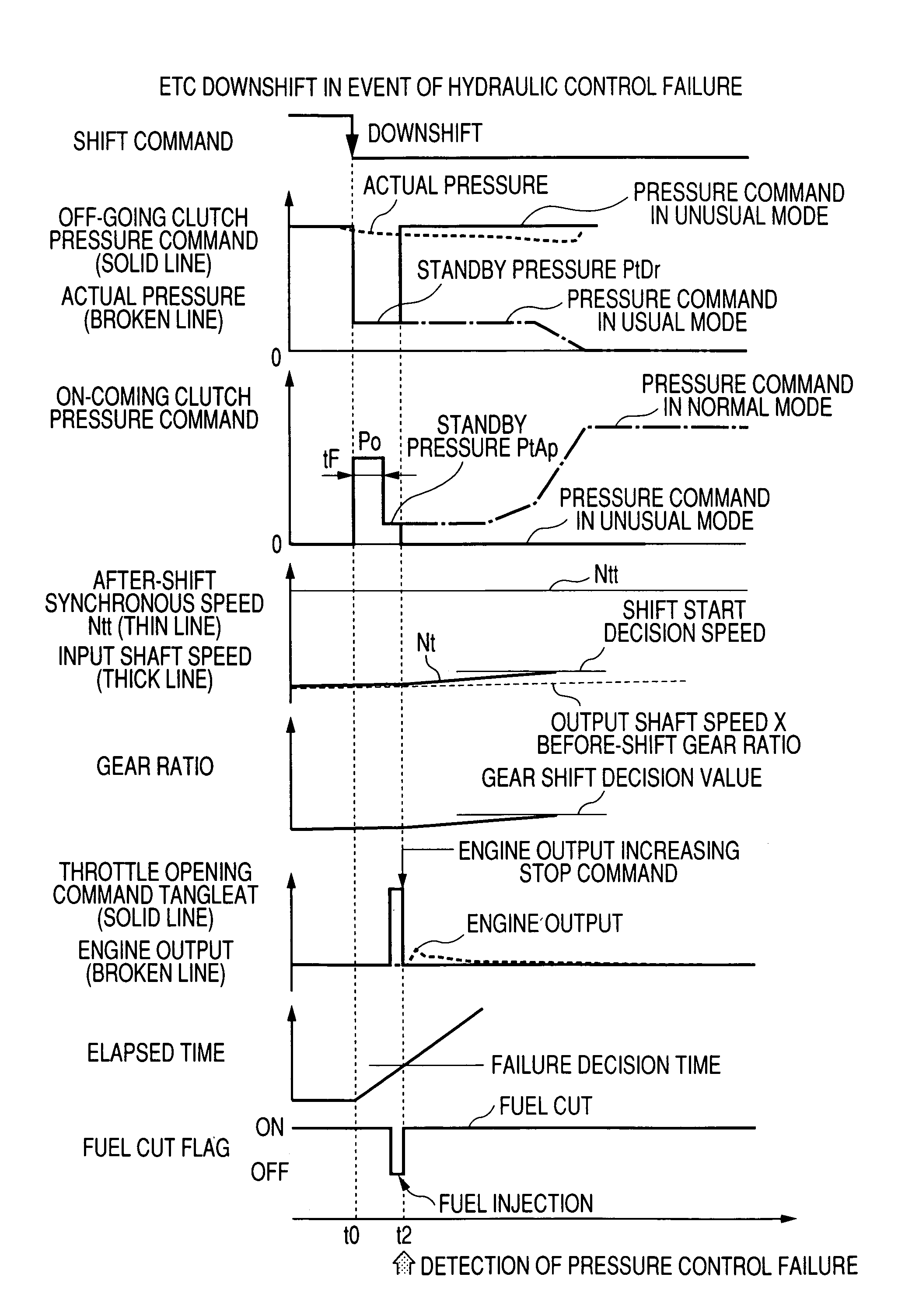
[0218]The engine control system of the first embodiment is designed to decide that a failure has occurred in the hydraulic pressure control for the automatic transmission 51 if an actual downshift is not detected when the elapsed time from the start of hydraulic pressure control has reached the failure decision time slightly longer than an expected time at which the automatic transmission 51 will initiate the downshift actually and immediately stop the engine output increasing control. The engine control system of the second embodiment is equipped with a hydraulic switch working to detect the fact that the hydraulic pressure acting on the off-going clutch lies within a lower range defined around the standby hydraulic pressure and designed to measure the elapsed time from the start of the hydraulic pressure control for a downshift, decide that a failure has occurred in the hydraulic pressure control when...

third embodiment

[0222]The engine control system of the third embodiment will be described below.

[0223]If the hydraulic pressure acting on the off-going clutch fails to drop to within the lower range after the start of the hydraulic pressure control to make a downshift in the automatic transmission 51, it may result in an interlocking in which the hydraulic pressure applied to the off-going clutch fails to drop, and that applied to on-coming clutch arises, so that they are engaged simultaneously. If such an interlocking is taken place upon downshifting of the transmission gearbox 55, it will, as demonstrated in FIG. 29, result in a drop in the input shaft speed Nt or the output shaft speed No of the transmission gearbox 55 due to deceleration of the vehicle.

[0224]The engine control system of the third embodiment is designed to inhibit the engine output increasing control using the above event. Specifically, the engine control system works to decide that the interlocking between the on-coming and off...


PUM


Abstract

An automotive automatic transmission control apparatus is provided which works to increase the power of an engine in response to a request to down-shift the gear of an automatic transmission for developing the engine braking. The control apparatus includes a fail-safe circuit working to stop increasing the power of the engine when a defect in operation of a transmission hydraulic control circuit is detected after the hydraulic control circuit starts to control the hydraulic pressures to achieve the downshift of the automatic transmission. This eliminates or alleviates a problem, such as unwanted acceleration of the vehicle during the control of the downshift in the transmission.

Description

CROSS REFERENCE TO RELATED DOCUMENT[0001]The present application claims the benefit of Japanese Patent Application No. 2004-239811 filed on Aug. 19, 2004, the disclosure of which is incorporated herein by reference.BACKGROUND OF THE INVENTION[0002]1. Technical Field of the Invention[0003]The present invention relates generally to an automotive automatic transmission controller equipped with a feature to increase an engine power for minimizing a shift shock occurring during downshift control executed according to a driver's deceleration intention to develop the engine braking.[0004]2. Background Art[0005]Most modern automotive automatic transmissions are designed to switch between hydraulic control lines to establish engagement and disengagement of frictional elements such as clutches and brakes selectively for achieving a desired one of speeds. When the accelerator of the vehicle is released fully during running on a downhill, but the engine braking is insufficient, the driver of th...

Claims


Application Information

Patent Timeline
Patent Type & Authority Patents(United States)
IPC IPC(8): B60W10/06B60W10/10F02D9/02F02D29/00F02D41/22F02P5/15F16H59/10F16H59/38F16H59/68F16H61/12F16H61/21F16H61/68F16H61/684F16H61/686F16H63/50
CPCB60W50/038F16H61/061F16H61/12F16H63/502F16H61/686Y10T477/669F16H2061/1224F16H2061/124F16H2200/0043F16H2200/2007B60W10/06B60W10/115F16H2061/1264Y10S477/906Y10T477/675Y10T477/68Y10T477/69
Inventor NAKAJIMA, NOBUYORIMURAKAWA, TAKAJIKOZAKI, TETSUJI
Owner DENSO CORP
Why Eureka
Try Eureka