Lightweight structure particularly for an aircraft

a technology for aircraft and light weight, applied in the field of light weight structure, can solve the problems of monolithic sheet metals, high production cost, and poor static strength characteristics of conventional fiber composite materials, and achieve the effects of improving damage tolerance, preventing crack propagation or crack formation, and slowing down crack propagation

Active Publication Date: 2007-10-23
AIRBUS OPERATIONS GMBH
View PDF28 Cites 13 Cited by
  • Summary
  • Abstract
  • Description
  • Claims
  • Application Information

AI Technical Summary

Benefits of technology

[0007]to improve a lightweight structure as described above in such a way that it will have a significantly better tolerance against damages, while keeping any weight increase to an acceptable minimum;
[0008]to substantially improve the crack fatigue characteristic of the lightweight structure, more specifically to reduce the crack propagation in such structures; and
[0010]The above objects have been achieved according to the invention by reinforcing strips adhesively bonded to the inwardly facing surface of the outer skin between the structural components of the frame structure or framework, such as stringers and ribs, wherein the reinforcing strips are made of a material that has a good tolerance against damages, for example by preventing or at least retarding crack propagation.
[0012]The above described arrangement of reinforcing strips improves the damage tolerance of such lightweight structures as an aircraft body skin in that the propagation, for example, of a fatigue crack is slowed down or even prevented in the area of the outer skin. Thus, the outer skin remains serviceable over a longer period of time, particularly where the reinforcing strips form a lattice structure.
[0013]It has been found that the improvement of slowing down crack propagation or preventing crack propagation or crack formation is equally achieved for lightweight structures made of laminated materials as well as of monolithic sheet materials. A significant slow down in the crack propagation has been achieved particularly in arranging the reinforcing strips in the above mentioned lattice work that is positioned between ribs and stringers of the aircraft body frame. More specifically, it has been found that the useful life of the lightweight structure can be increased five-fold because of the slow down of the crack propagation in the outer skin. More specifically, the reinforcing strips in the form of so-called “doublers” between two neighboring stringers or two ribs slow down the crack propagation in the outer skin. It has further been found, based on comparing a single layer monolithic sheet metal skin with a multi-layer metallic laminated material both of which are equipped with reinforcing strips according to the invention and formed as a lattice structure, that the propagation of fatigue cracks is significantly reduced in the laminated material if the fatigue cracks have an initial length corresponding to the spacing between two neighboring stringers. On the other hand, the crack propagation is noticeably higher in the laminated materials than in the monolithic sheet metal skin if the fatigue crack has a length of up to twice the spacing between two stringers.
[0014]The advantages of the invention are seen in a weight reduction, particularly in aircraft body skin shells which must have high damage tolerances. These tolerances are particularly significant in the shells forming part of the upper portion of an aircraft body. According to the invention using additional reinforcing strips made of a damage tolerant material, a weight reduction is possible to a significant extent because it is now possible to reduce the thickness of the sheet metal skin by about 20% compared to conventional skin thicknesses of sheet metal skins. Such a 20% reduction in sheet thickness results in a significantly reduced weight of the lightweight structure.

Problems solved by technology

Conventional fiber composite materials have, to some extent, static strength characteristics that are not as good as such static strength characteristics of monolithic materials.
Furthermore, the production of fiber reinforced laminated materials is subject to a substantial effort and expense compared to monolithic sheet metals, due to the needed preparation of thin sheet metal layers for the adhesive bonding with additional prepreg films and due to the necessity of manually positioning and preparing for the following adhesive bonding step.
As a result, the production costs for laminated composite materials can be significantly higher than the costs for producing monolithic sheet metals.

Method used


Image

  • Lightweight structure particularly for an aircraft
  • Lightweight structure particularly for an aircraft
  • Lightweight structure particularly for an aircraft

Examples


Embodiment Construction

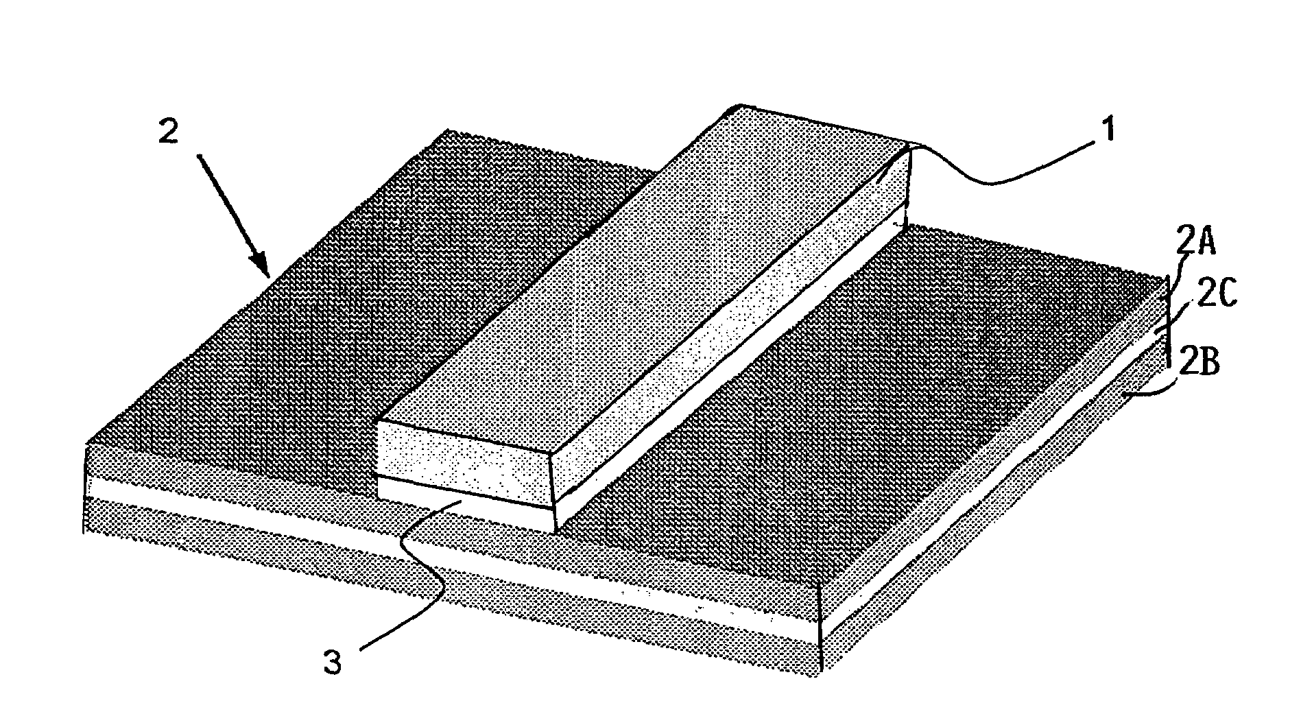
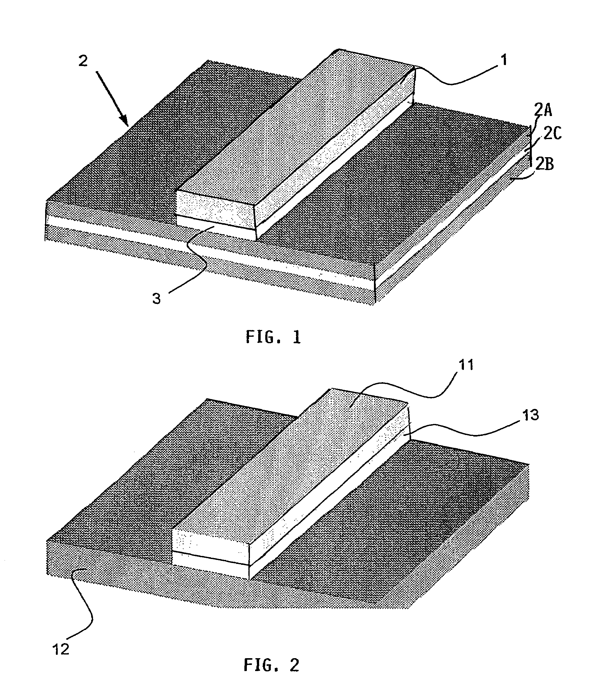
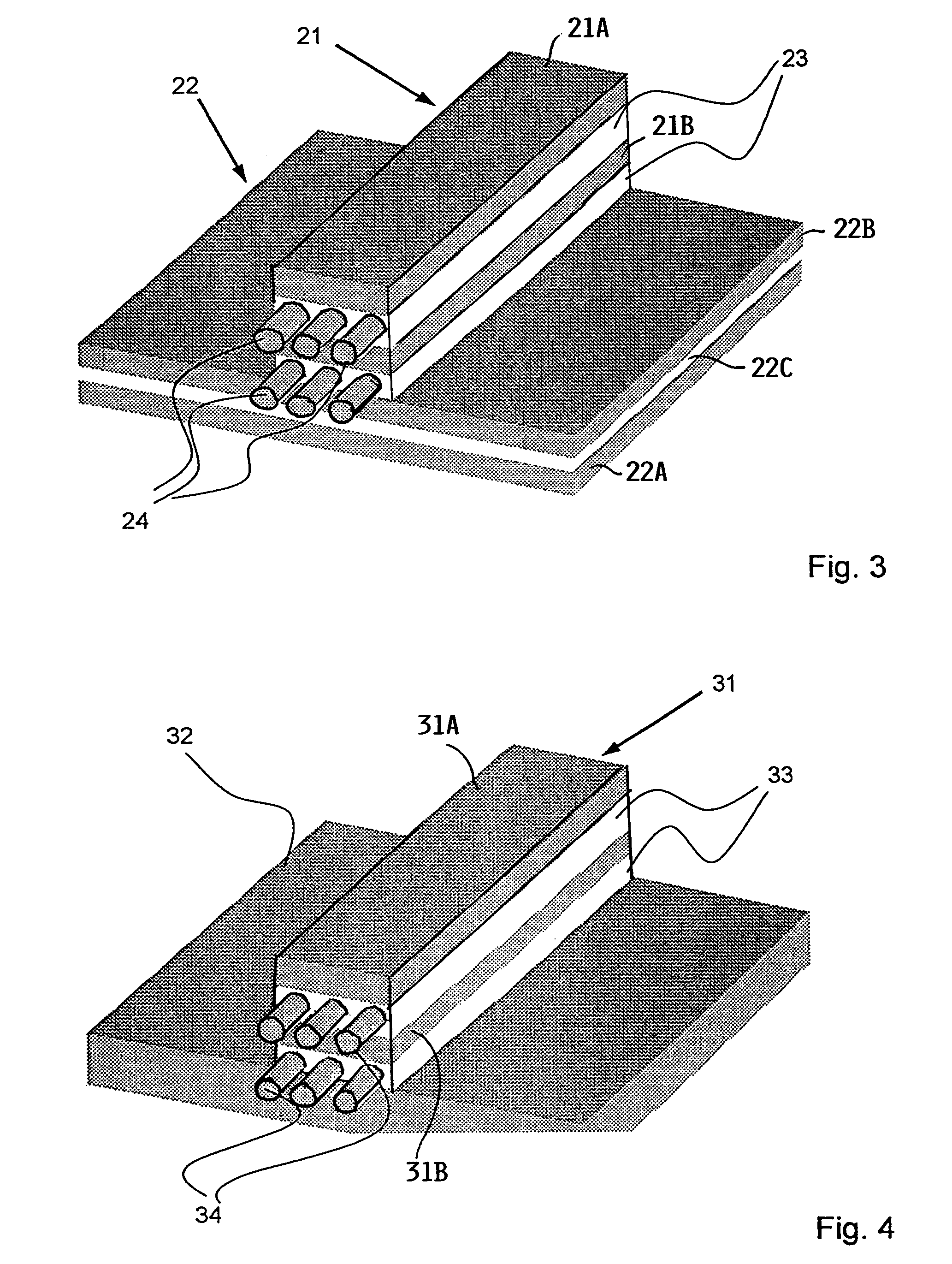
[0022]Referring first to FIG. 6 for an overview of the invention when it is used in an aircraft body, longitudinally extending stringers S1, S2 form with circumferentially extending ribs an aircraft body frame or framework FW. An outer skin OS covers the framework FW outwardly. In a preferred embodiment according to the invention a lattice work LW is adhesively bonded to the inwardly facing side of the outer skin between the ribs R1, R2 and the stringers S1, S2. As shown the lattice work LW of the preferred embodiment comprises rows R and columns C of reinforcing strips adhesively bonded to the inner surface of the outer skin OS and to each other. While the lattice work of reinforcing strips is preferred, the reinforcing strips may be arranged only as columns or only as rows. In any such embodiments the angular orientation of the columns C and / or rows R relative to the stringers and relative to the ribs will be such that the reinforcing strips cross propagation directions of cracks ...


PUM

PropertyMeasurementUnit
lengthaaaaaaaaaa
thicknessaaaaaaaaaa
widthaaaaaaaaaa

Abstract

An outer skin of an aircraft body is supported by a frame of longitudinal stringers and circumferential ribs or frame elements interconnecting the stringers. Additionally, the outer skin is strengthened by a reinforcing strip formation adhesively bonded to the inwardly facing surface of the outer skin between the ribs and stringers. The reinforcing strips are made of a material that is damage tolerant, for example high strength aluminum alloys and fiber composite materials are suitable for making the reinforcing strip formation. The reinforcing strips of the strip formation may extend in parallel to the stringers and / or the ribs and preferably form a lattice work. The reinforcing strips need not cross each other at right angles but should cross a crack propagation direction in the outer skin.

Description

PRIORITY CLAIM[0001]This application is based on and claims the priority under 35 U.S.C. §119 of German Patent Application 103 30 709.5, filed on Jul. 8, 2003, the entire disclosure of which is incorporated herein by reference.FIELD OF THE INVENTION[0002]The invention relates to a lightweight structure such as an outer skin secured to a frame structure of an aircraft body.BACKGROUND INFORMATION[0003]Lightweight structures particularly as used in the aircraft technology and in spacecraft technology, frequently comprise an outer skin, the inwardly facing surface of which is reinforced by a frame structure which herein is referred to as a “two-dimensional” stiffening, compared to the entire body which is “three-dimensional”. The aircraft body is constructed of longitudinally extending stringers and circumferentially extending ribs to which the outer skin is secured, whereby the skin is reinforced by the stringers and ribs. In designing such lightweight structures special attention is p...

Claims


Application Information

Patent Timeline
Patent Type & Authority Patents(United States)
IPC IPC(8): D04H1/00D04H13/00D04H3/00D04H5/00B32B3/08B32B3/14B32B15/08
CPCB32B3/08B32B15/08B32B3/14Y10T428/249924B32B2311/18B32B15/20B32B2260/021B32B2260/046B32B27/38B32B2305/08B32B15/092B32B7/12
Inventor SCHMIDT, HANS-JUERGENVICHNIAKOV, ALEXEI
Owner AIRBUS OPERATIONS GMBH
Why Eureka
Try Eureka