Optical device for surface-generated fluorescence

a technology of optical devices and fluorescence, which is applied in the direction of fluorescence/phosphorescence, luminescent dosimeters, optical radiation measurement, etc., to achieve the effect of efficient transmission of emitted light, efficient separation of excitation light, and increasing signal/background ratio

Active Publication Date: 2007-10-23
OERLIKON SURFACE SOLUTIONS AG PFAFFIKON
View PDF41 Cites 2 Cited by
  • Summary
  • Abstract
  • Description
  • Claims
  • Application Information

AI Technical Summary

Benefits of technology

[0028]In another embodiment of the present invention the intermediate layer system is designed to efficiently separate the excitation light from the emitted light thereby increasing the signal / background ratio.
[0029]In the case of front surface excitation and rear surface readout, the intermediate layer system needs to be designed to reflect the excitation light and to transmit the emitted light efficiently.
[0030]In the case of front surface excitation and front surface readout the intermediate layer system needs to be designed in such a way that the excitation light is transmitted through the intermediate layer system whereas the emitted light is reflected according to the first embodiment of the present invention. In the case of rear surface excitation the intermediate layer system needs to be designed in such a way that it efficiently transmits the excitation light. In this case in order to separate excitation light from emitted light rear surface readout is applied and the intermediate layer system is designed in such a way that it transmits the emitted light efficiently.

Problems solved by technology

If possible this results in waveguiding.

Method used


Image

  • Optical device for surface-generated fluorescence
  • Optical device for surface-generated fluorescence
  • Optical device for surface-generated fluorescence

Examples


Embodiment Construction

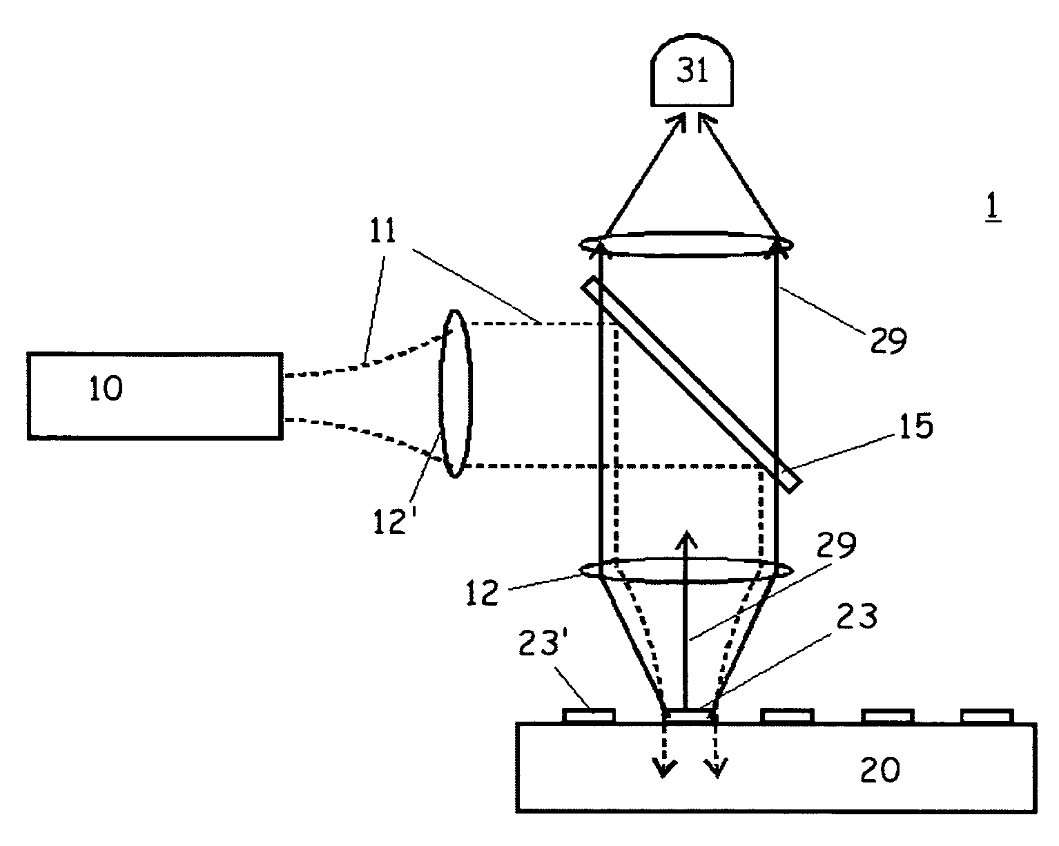
[0041]In the first example reading the fluorescence signal, a sample substrate is to be placed in a laserscanner, as illustrated in FIG. 1:

[0042]A light source 10, such as for example a laser, produces an stimulating beam 11. The stimulating beam 11 is preferably a collimated beam of monochromatic coherent light. However, a noncoherent source, such as a light emitting diode (LED) could be used and a noncollimated source could be coupled to collimating optics to create a collimated beam. If the stimulating beam 11 is not monochromatic, it may be directed through a filter to reduce any unwanted wavelengths.

[0043]The stimulating beam 11 is then directed through lens systems 12, 12′ and a beam splitter 15 onto the surface of the sample substrate 20. Any scanning mechanism that produces a two-dimensional scan may be used to move the substrate along orthogonal axis in plane with the surface of the sample substrate.

[0044]The lens system 12 provides coaxial illumination of the sample substr...


PUM

PropertyMeasurementUnit
wavelength bandaaaaaaaaaa
wavelengthaaaaaaaaaa

Abstract

A sample substrate adapted for use with electromagnetic excitation light includes a base and a layer system. The layer system includes a multilayer interference coating with at least two layers wherein the thicknesses of the layers ensure that light emitted by a fluorescent sample material disposed on top of said multilayer interference coating is reflected. Light directed to a fluorescent sample material disposed on the substrate causes light to be emitted from the sample. The layer system includes a multilayer interference coating with at least two layers wherein thicknesses of the layers cause separation of the excitation light from the emitted light.

Description

FIELD OF THE INVENTION[0001]The present invention relates to a process for amplifying a electromagnetic signal emitted by an areal sample supported by a support in response to an excitation signal. It also relates to a device amplifying the electromagnetic signal emitted by such a sample.PRIOR ART[0002]Measurement by fluorescence, phosphorescence and luminescence is a method of measurement used in many technical fields. It is used particularly to operate devices of chemical and / or biological analysis often referred to as bio-chips. Measuring biological activity with a chip of this kind is done by measuring an emitted electromagnetic signal in form of fluorescence, phosphorescence or luminescence emission of a molecule fixed to the biological sample, which is presented in the form of a surface coating, using for example an epifluorescence microscope, a scanner, a fluorimeter. Throughout this disclosure the emitted electromagnetic signal will be referred to as emitted light.[0003]To p...

Claims


Application Information

Patent Timeline
Patent Type & Authority Patents(United States)
IPC IPC(8): G01N21/00G01J1/58G01N21/64
CPCG01N21/6428G01N21/6452G01N2021/6471
Inventor WIKI, MAXEDLINGER, JOHANNES
Owner OERLIKON SURFACE SOLUTIONS AG PFAFFIKON
Why Eureka
Try Eureka