
Permanent magnet solenoid pump for an implantable therapeutic substance delivery device

a magnet solenoid pump and implantable technology, applied in the field of medical devices, can solve the problems of consuming 90% or more of the available battery power, limiting the period of pump implanting, and consuming energy. , to achieve the effect of energy efficien

Inactive Publication Date: 2007-10-30
MEDTRONIC INC
View PDF58 Cites 151 Cited by
  • Summary
  • Abstract
  • Description
  • Claims
  • Application Information

AI Technical Summary

Benefits of technology

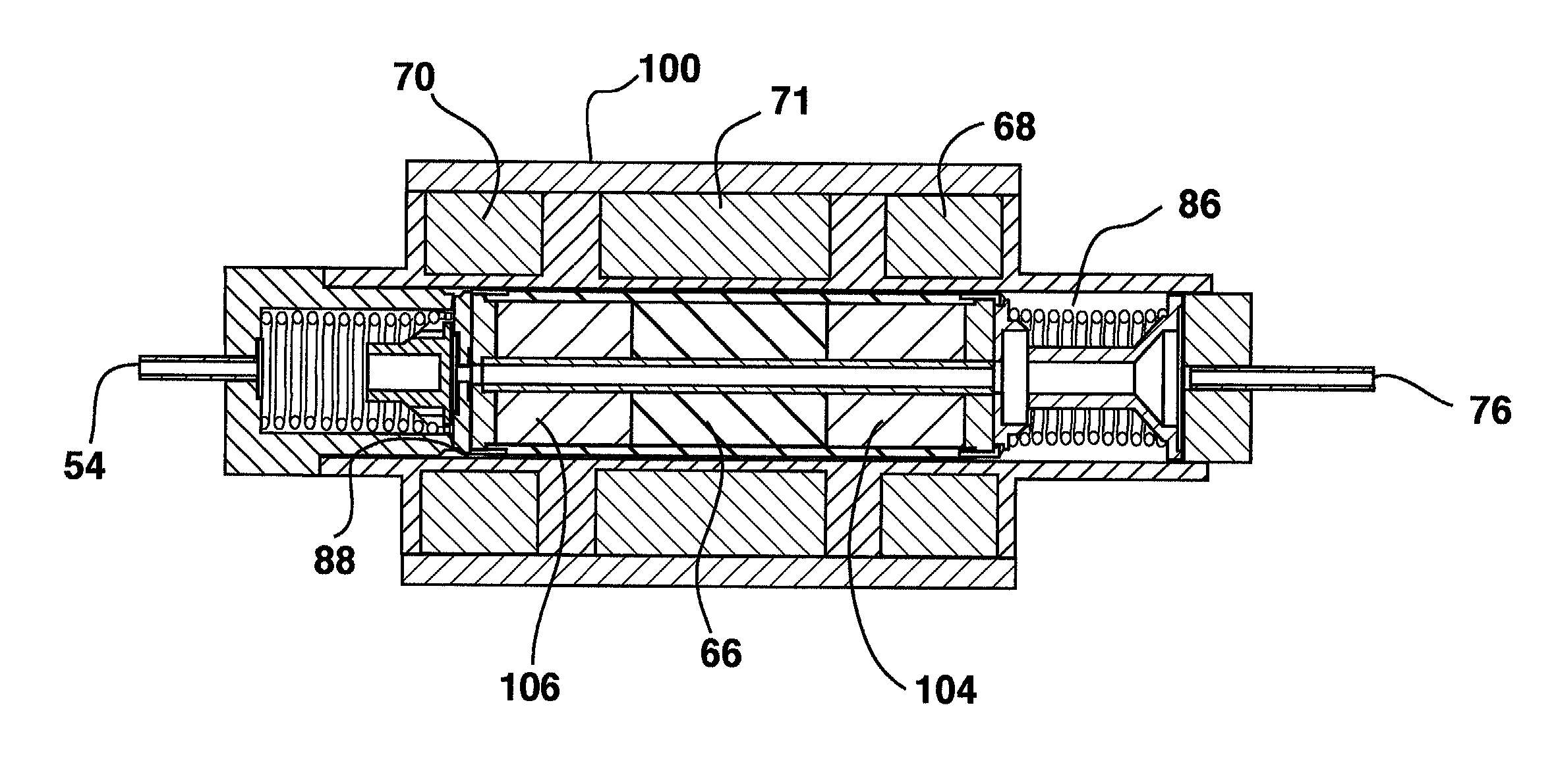
[0009]A permanent magnet solenoid pump for an implantable therapeutic substance delivery device embodiment is energy efficient, accurate, small, compatible with therapeutic substances, and has many other improvements. The permanent magnet solenoid pump is coupled to electronics and coupled to a therapeutic substance reservoir outlet to pump therapeutic substance from the therapeutic substance reservoir through an infusion outlet at a programmed rate. The permanent magnet solenoid pump is carried in a therapeutic substance delivery device that has a housing, a therapeutic substance reservoir coupled to the housing, a power source carried in the housing, and electronics carried in the housing and coupled to the power source. Many embodiments of the permanent magnet solenoid pump and its methods of operation are possible.

Problems solved by technology

Reliable and accurate operation of the drug pump is important because both inadequate and unintended therapeutic substance delivery can create patient complications.
In electrically powered implantable drug pumps, the period the pump can be implanted is often limited by factors such as battery consumption, corrosive damage, and mechanical wear.
The relative large size of some implantable drug pumps can limit locations where the device can be implanted in a patient.
In an implantable therapeutic substance delivery device having a peristaltic pump, the peristaltic pump is typically one of the largest components in the device and can consume 90% or more of the available battery power.
The flexible tube used in a peristaltic pump is typically permeable to some therapeutic substance components such as water that can then infiltrate into the hermetically sealed housing and cause corrosion.
Additionally, the flexible tube can expand resulting in decreased accuracy.
Solenoid piston pumps such as variable reluctance solenoid pumps and permanent magnet solenoid pumps can have disadvantages compared to peristaltic pumps such as higher energy consumption, difficulty with passing air, difficulty with valve sealing, and therapeutic substance material compatibility.
Energy consumption of a reluctance solenoid pump can be relatively high because of pump construction and nonlinear piston force.
Reluctance solenoid pumps can be constructed with a large pole piece that can cause fluid energy loss.
Reluctance solenoid pump nonlinear piston force caused when piston force increases as the poles close the gap can also reduce pumping efficiency.
Passing air can be difficult for solenoid pumps because of large dead volumes created by valve geometries.
Sealing valves can be difficult because passively operated valves can unintentionally open under some circumstances creating safety concerns.
Therapeutic substance material compatibility can be difficult to achieve in some solenoid pumps because of the pumping components that are in contact with the therapeutic substance.

Method used


Image

  • Permanent magnet solenoid pump for an implantable therapeutic substance delivery device
  • Permanent magnet solenoid pump for an implantable therapeutic substance delivery device
  • Permanent magnet solenoid pump for an implantable therapeutic substance delivery device

Examples


Embodiment Construction

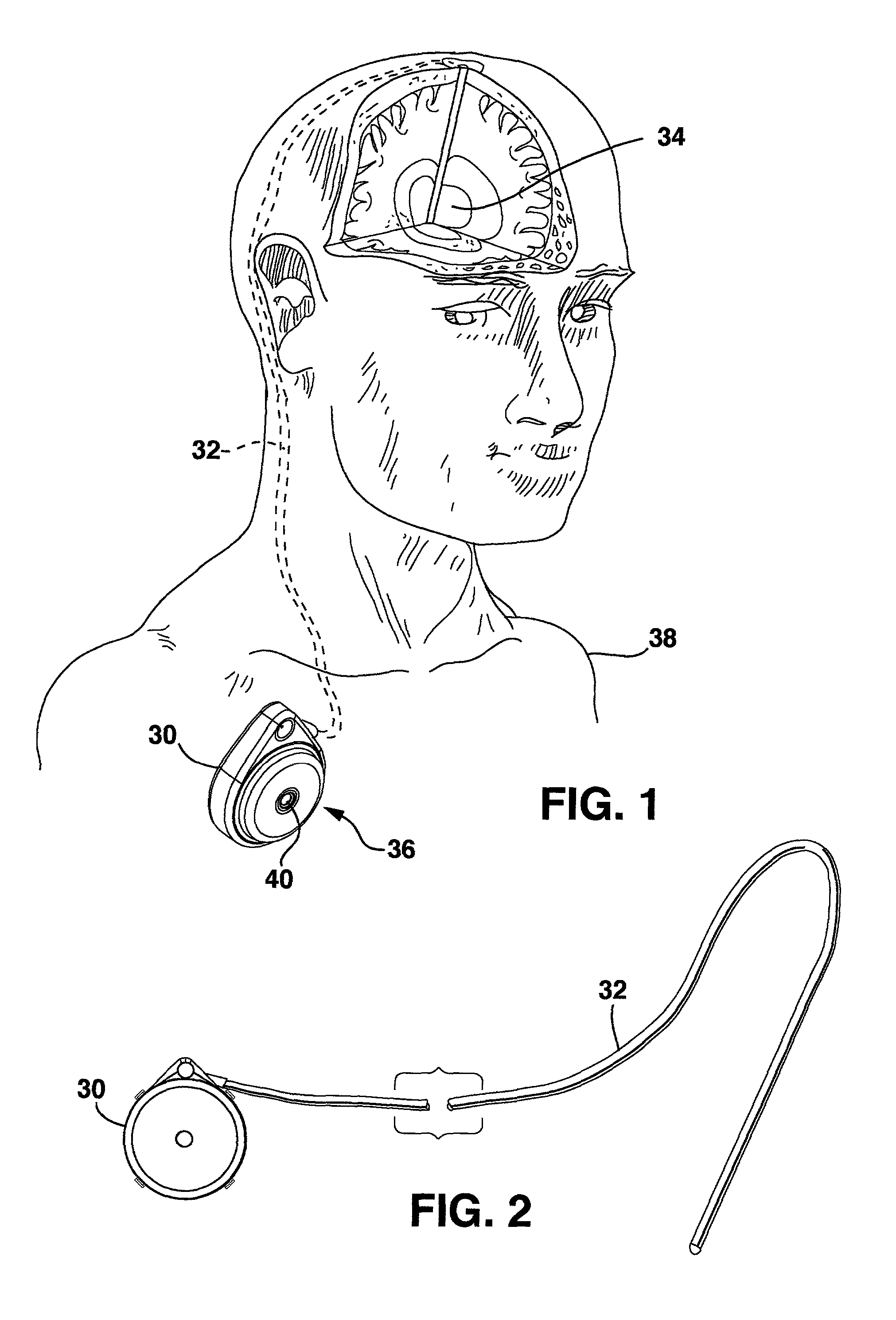
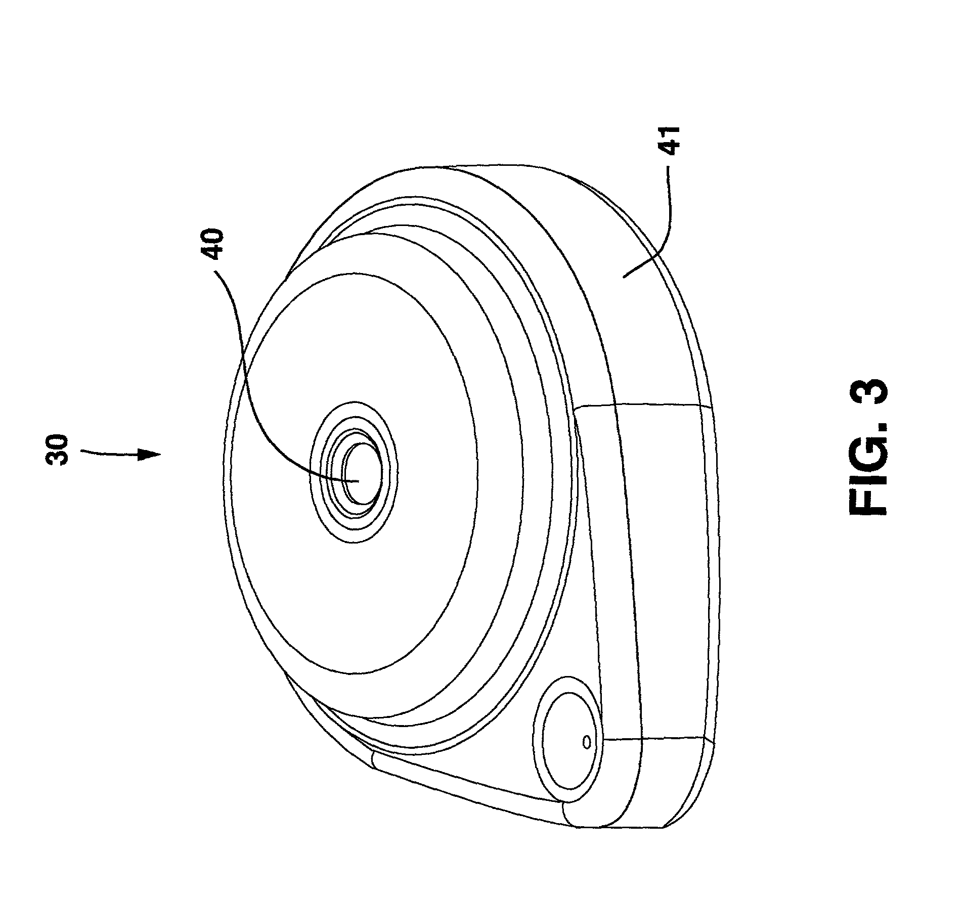
[0030]FIG. 1 shows the environment of an implantable medical device known as an implantable therapeutic substance delivery device 30, also known as a drug pump, having a permanent magnet solenoid pump embodiment. The therapeutic substance delivery device 30 can be used for a wide variety of therapies such as pain, spasticity, cancer, and many other medical conditions. The implantable therapeutic substance delivery device 30 is typically implanted by a clinician such as a surgeon in a sterile surgical procedure performed under local, regional, or general anesthesia. Before implanting the therapeutic substance delivery device 30, a catheter 32 is typically implanted with the distal end position at the desired therapeutic substance delivery site 34 and the proximal end tunneled to the location where the therapeutic substance delivery device 30 is to be implanted. The catheter 32 and the therapeutic substance delivery site 34 can generate a back pressure during infusion known as the inf...


PUM


Abstract

A medical device known as an implantable therapeutic substance delivery device is configured for implanting in humans to deliver a therapeutic substance such as pharmaceutical compositions, genetic materials, and biologics to treat a variety of medical conditions such as pain, spastisity, cancer, and many other conditions. The therapeutic substance delivery device has a permanent magnet solenoid pump that is energy efficient, accurate, small, compatible with therapeutic substances, and has many other improvements. The implantable therapeutic substance delivery device has a housing, a therapeutic substance reservoir, a power source, electronics, and a permanent magnet solenoid pump. The therapeutic substance reservoir is configured to contain a therapeutic substance and is coupled to the housing. The power source is carried in the housing to power the electronics and solenoid pump. The electronics are coupled to the solenoid pump and the solenoid pump is coupled to the therapeutic substance reservoir. The permanent magnet solenoid pump is configured for pumping therapeutic substance from the therapeutic substance reservoir through an infusion outlet at a programmed infusion rate. Many embodiments of the permanent magnet solenoid pump and its methods of operation are possible.

Description

RELATED APPLICATIONS[0001]This application claims the benefit of provisional application U.S. Ser. No. 60 / 282,775, filed Apr. 10, 2001, entitled “PERMANENT MAGNET SOLENOID PUMP FOR AN IMPLANTABLE THERAPEUTIC SUBSTANCE DELIVERY DEVICE”, by James M. Olsen.[0002]This disclosure is related to the following co-pending applications entitled “LOW PROFILE INLET VALVE FOR A PISTON PUMP THERAPEUTIC SUBSTANCE DELIVERY DEVICE” by inventor Olsen (Application No. 60 / 282,778; filed Apr. 10, 2001) and “IMPLANTABLE THERAPEUTIC SUBSTANCE DELIVERY DEVICE HAVING A PISTON PUMP WITH AN ANTI-CAVITATION VALVE” by inventor Olsen (Application No. 60 / 282,777; filed Apr. 10, 2001) which are not admitted as prior art with respect to the present disclosure by its mention in this section.BACKGROUND OF THE INVENTION[0003]This disclosure relates to a medical device and more particularly to an implantable therapeutic substance delivery device with a piston operated pump.[0004]The medical device industry produces a w...

Claims


Application Information

Patent Timeline
IPC IPC(8): A61K9/22A61M1/00A61M5/142
CPCA61M5/14276A61M5/14216
Inventor OLSEN, JAMES M.
Owner MEDTRONIC INC
Learn More