
Mirror assembly for vehicle

a rearview mirror and mirror technology, applied in the direction of optical elements, instruments, transportation and packaging, etc., can solve the problems of less economical two-part, non-unitary casing and bezel design, and difficulty in installing or inserting other accessories or components into the casing, etc., to facilitate the addition of electronic accessories, low cost, and minimal additional investment

Inactive Publication Date: 2007-10-30
MAGNA MIRRORS OF AMERICA INC
View PDF21 Cites 552 Cited by
  • Summary
  • Abstract
  • Description
  • Claims
  • Application Information

AI Technical Summary

Benefits of technology

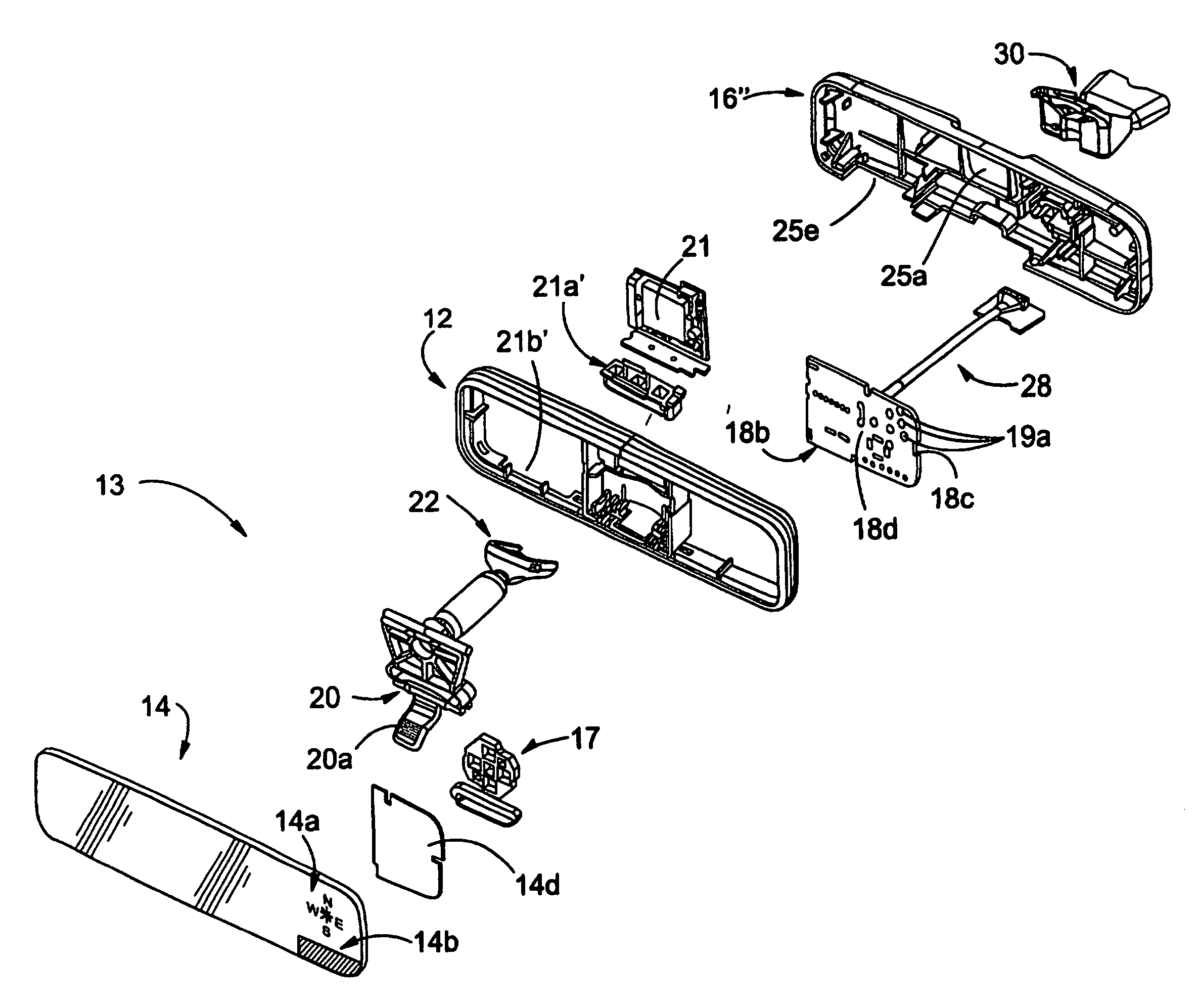
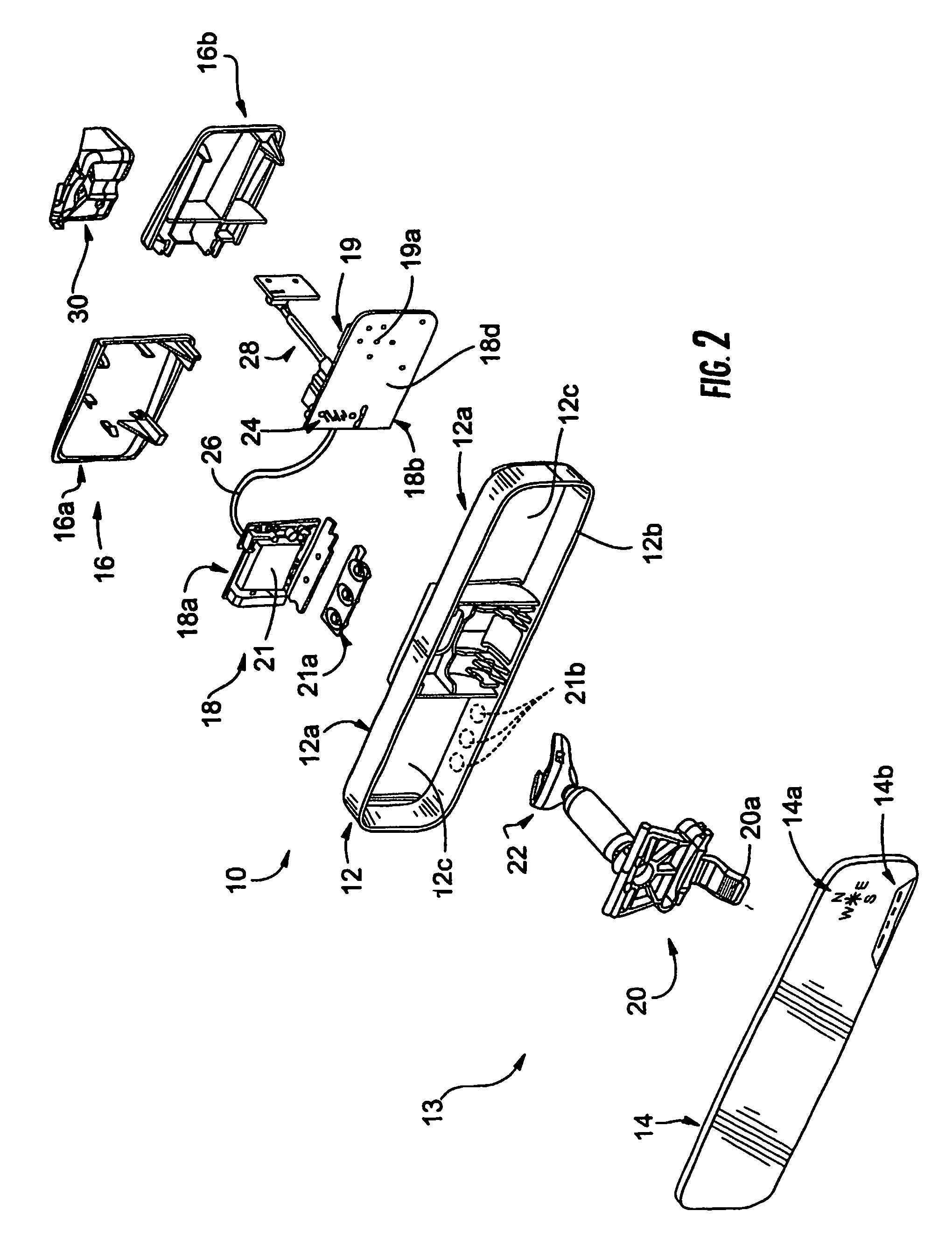
The present invention provides an interior rearview mirror assembly with one or more electronic accessories or features. These accessories can be attached to the rear portion of the mirror holder or bezel after the reflective element is inserted and the holder has cooled and shrunk. The accessories can include a compass sensor, display, tire pressure monitoring system receiver / control circuitry, antenna, garage door opener, or any other accessory and associated circuitry. The cap portion or portions can be detachably attached to the mirror holder or first molding or bezel portion, or non-detachably attached such as by adhesive or heat staking. The invention allows for easy addition of various features without significant additional investment and facilitates the addition of customization options for customers.

Problems solved by technology

Because the reflective element is inserted into the casing while the casing is hot (such as after being freshly molded), the timing for the insertion process may be limited.
Thus, it may be difficult to install or insert other accessories or components into the casing before the casing cools and shrinks.
Although practical, this involves a less economical two-part, non-unitary casing and bezel design.

Method used


Image

  • Mirror assembly for vehicle
  • Mirror assembly for vehicle
  • Mirror assembly for vehicle

Examples


Embodiment Construction

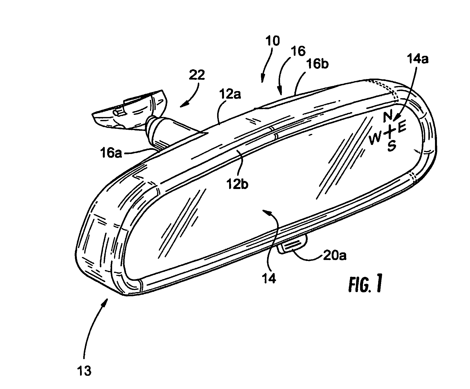
[0049]Referring now to the drawings and the illustrative embodiments depicted therein, an interior rearview mirror assembly or modular prismatic rearview mirror assembly 10 for a vehicle includes a reflective element assembly portion 13 including a mirror holder 12 and a reflective element 14 (FIG. 1) positioned at and at least partially within the mirror holder and / or bezel portion, that preferably is molded from a polyolefin material, such as a polypropylene material or the like. Mirror assembly 10 includes a plastic molded cap or cap portion 16, preferably molded from an ABS material, an engineering resin material, such as a filled or unfilled nylon material, or the like (and may be integrally molded with metallic or ceramic materials or inserts or the like to provide mechanical bracing and enhanced structural rigidity). Cap portion 16 is mountable or attachable to a rear portion or open portion 12a of mirror holder 12, and may include an accessory or feature or the like, such as...


PUM


Abstract

An interior rearview mirror assembly for a vehicle includes a reflective element assembly portion and at least one cap portion adapted to attach to the reflective element assembly portion. The reflective element assembly portion includes a reflective element. The reflective element assembly portion comprises a first molding that encompasses at least a perimeter portion of the reflective element. The first molding is formed by molding a first resinous material having a tool shrinkage factor equal to or greater than about 1 percent. The cap portion comprises at least one second molding formed by molding a second resinous material having a tool shrinkage factor of less than or equal to about 1 percent. The cap portion preferably includes internal structure for supporting at least one accessory.

Description

CROSS REFERENCE TO RELATED APPLICATIONS[0001]The present application is a 371 U.S. national phase application of PCT Application No. PCT / US2004 / 015424, filed May 18, 2004, which claims benefit of U.S. provisional applications, Ser. No. 60 / 471,546, filed May 19, 2003; Ser. No. 60 / 525,537, filed Nov. 26, 2003; and Ser. No. 60 / 556,259, filed Mar. 25, 2004, which are hereby incorporated herein by reference in their entireties.FIELD OF THE INVENTION[0002]The present invention relates generally to the field of interior rearview mirror assemblies for vehicles and, more particularly, to interior rearview mirror assemblies which incorporate an accessory or feature, particularly an electronic accessory or feature.BACKGROUND OF THE INVENTION[0003]The base level mirror for a vehicle is often a prismatic mirror assembly, which may provide a low cost mirror for the vehicle. The mirror assembly is often economically assembled by snapping or inserting the toggle assembly and prismatic reflective el...

Claims


Application Information

Patent Timeline
Patent Type & Authority Patents(United States)
IPC IPC(8): G08B5/00B60Q1/00G02B5/00B60K35/00B60RB60R1/12B60R11/00B60R11/02G02B7/182
CPCB60K35/00B60R1/02B60R1/04B60R1/12G02F1/157G02F1/01B60R11/02B60K2350/927B60R11/0235B60R2001/1215B60R2011/0033B60K35/60B60K2360/777B60K35/10B60K35/28B60K35/21B60K35/53G02B5/0808B60R1/086B60R1/1207B60R1/088
Inventor UKEN, JOHN TKARNER, LEEHOOK, RICHARD RLYNAM, NIALL R
Owner MAGNA MIRRORS OF AMERICA INC
Learn More