Portable, digital X-ray apparatus for producing, storing, and displaying electronic radioscopic images

a digital x-ray and electronic technology, applied in the direction of material analysis using wave/particle radiation, x/gamma/cosmic radiation measurement, instruments, etc., can solve the problems of affecting the optical design of the mirror, the above approaches are difficult to use in the mirror-folded system, and the optical portion is weakened, so as to reduce the effect, increase the fraction of light emitted, and enhance the optical portion

Inactive Publication Date: 2007-10-30
LEIDOS
View PDF37 Cites 13 Cited by
  • Summary
  • Abstract
  • Description
  • Claims
  • Application Information

AI Technical Summary

Benefits of technology

[0009]The present invention enhances the optical portion, or “imager”, of an X-ray radiographic or similar optical imaging system by increasing the fraction of light emitted from an X-ray converter screen that is directed into the collection cone of an objective lens, while at the same time reducing the effects of light emitted from the X-ray converter screen (which comprises a diffuse phosphor screen) which leaves the screen in a direction that is not captured by the lens. That is, the invention reduces the amount of light that is permitted to scatter within the imager, and also suppresses any light that does scatter within the imager. By reducing the amount of scattered light, and by suppressing what light does scatter, the collection cone of the objective lens thus receives a greater portion of the emitted light, and the optical system is thus able to produce a brighter image having improved contrast than has heretofore been achievable.

Problems solved by technology

Virtually all optical designs are plagued by the problem of light outside of the capture cone of the lens hitting other features within the optical system and being scattered back into the image.
Unfortunately, the above approaches are very difficult to use in a mirror folded system, such as is used for many X-ray imaging systems, including the present invention.
Further, if one wants to restrict the depth of the optical system (which is the case with the present invention) by using a mirror angle of 45 degrees or less, the problems of containing the light emitted at angles that would normally not fall into the collection cone and keeping this light from reflecting back onto the diffuse phosphor surface (where it may then bounce back into the collected beam) becomes virtually impossible.

Method used


Image

  • Portable, digital X-ray apparatus for producing, storing, and displaying electronic radioscopic images
  • Portable, digital X-ray apparatus for producing, storing, and displaying electronic radioscopic images
  • Portable, digital X-ray apparatus for producing, storing, and displaying electronic radioscopic images

Examples


Embodiment Construction

[0045]The following description is of the best mode presently contemplated for carrying out the invention. This description is not to be taken in a limiting sense, but is made merely for the purpose of describing the general principles of the invention. The scope of the invention should be determined with reference to the claims.

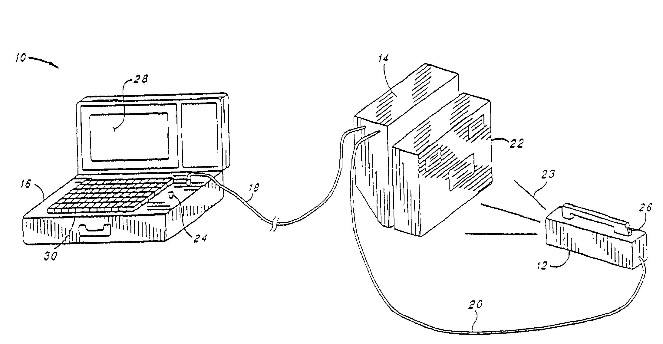
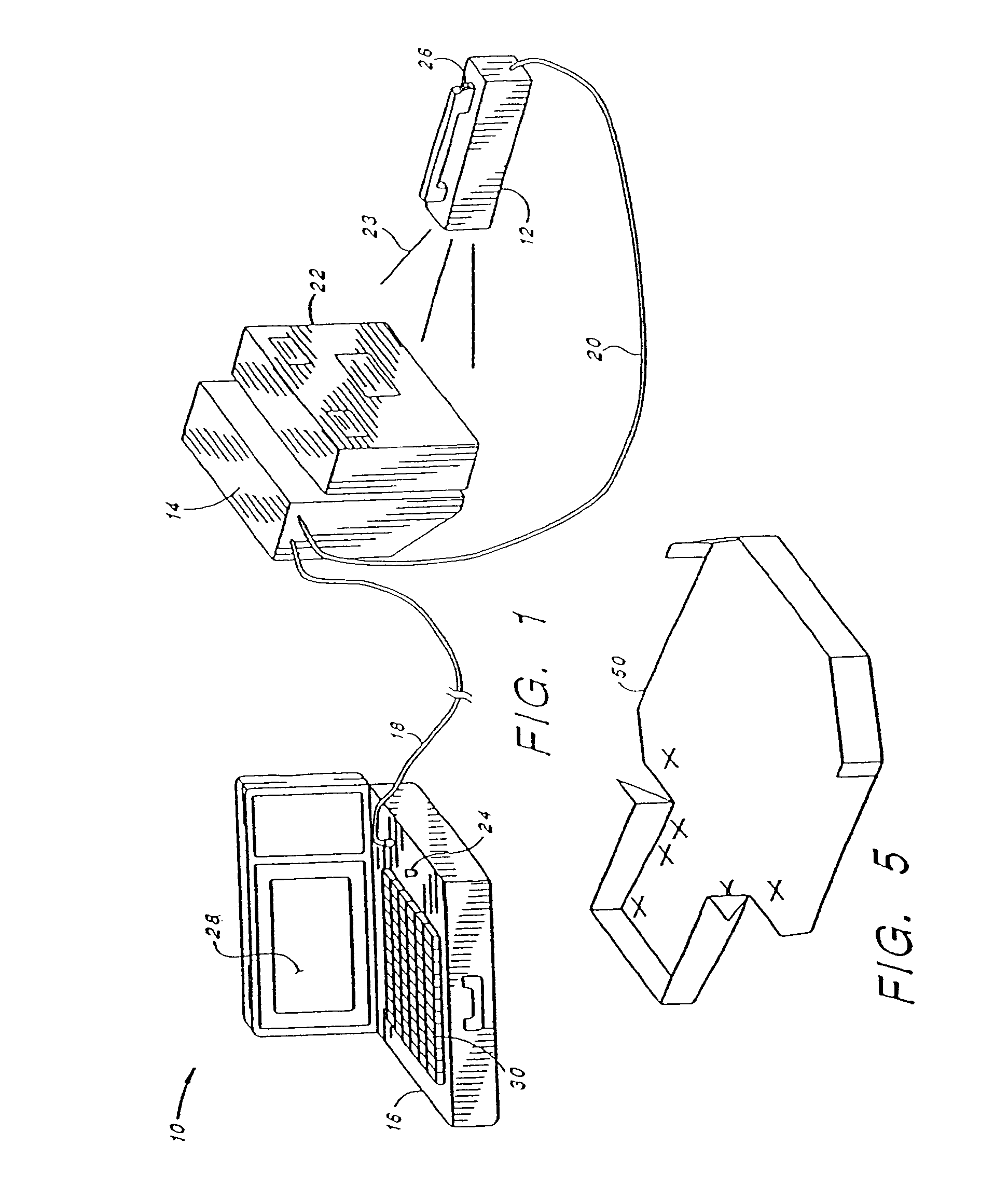
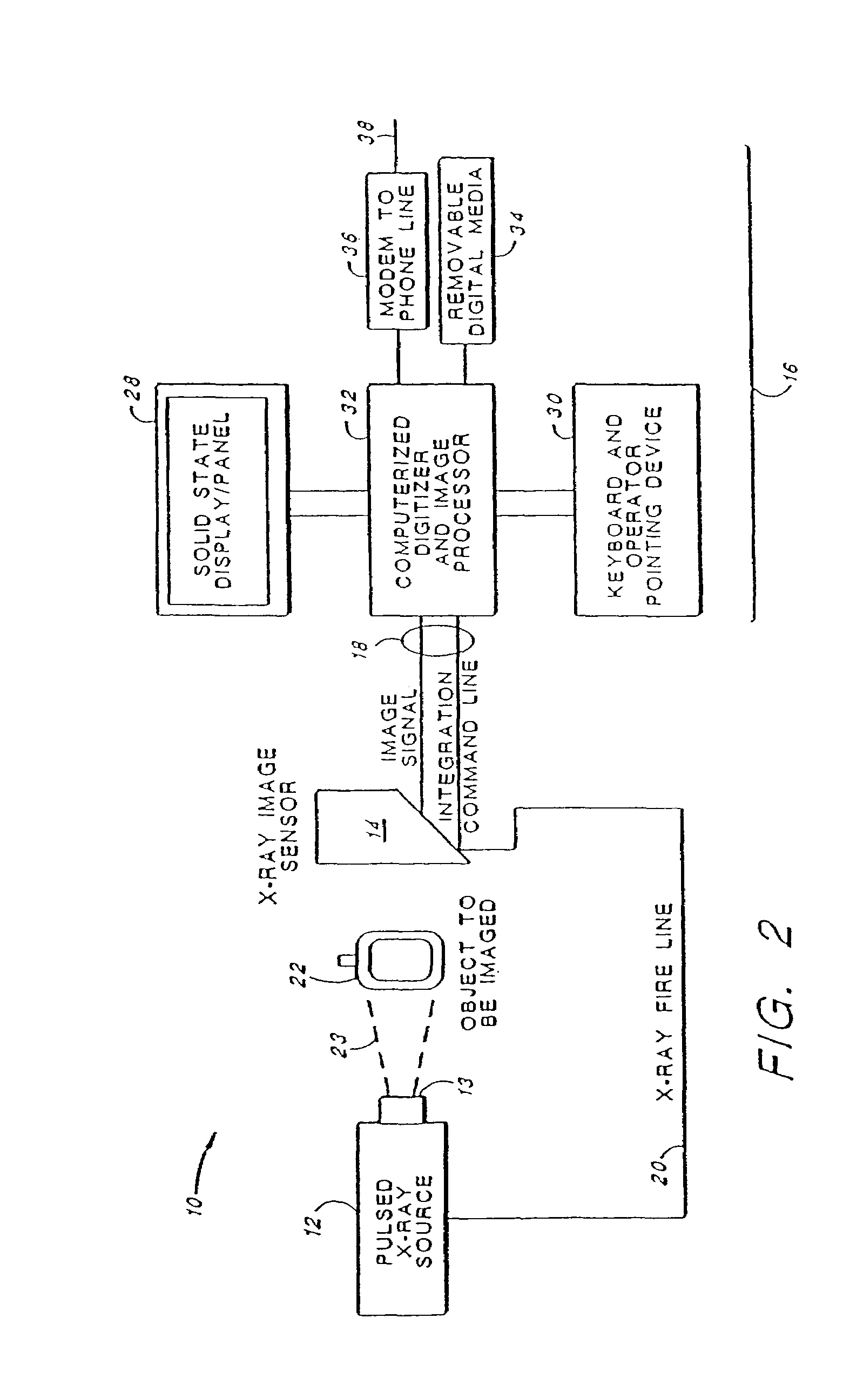
[0046]Turning first to FIG. 1, there is shown an imaging system 10 made in accordance with the present invention. The system 10 includes three main subsystems: (1) a portable X-ray source 12, (2) an imager 14, and (3) a Display / Control Unit 16. The three subsystems are interconnected with two cables. A first cable 18 is a “long” cable and is connected between the Display / Control unit 16 and the imager 14. The long cable may be as long as 180 feet. A second cable 20 is a “short” cable that is connected between the imager 14 and the X-ray source 12. The short cable is typically less than 10 feet in length.

[0047]Advantageously, the system 10 is portable, which ...


PUM


Abstract

A portable, self-contained, electronic radioscopic imaging system uses a pulsed X-ray source, a remote X-ray sensor, and a self-contained, display and controller unit to produce, store, and/or display digital radioscopic images of an object under investigation. The pulsed X-ray source transmits a burst of narrow pulses of X-rays at the object being investigated at a low repetition rate. The X-ray sensor utilizes an X-ray scintillating screen in combination with either an integrating CCD camera, or an active matrix of thin film transistors and sample-and-hold photodiodes, to produce an integrated signal representative of the accumulated number of flashes of radiation that are sensed in a given pixel area of the scintillating screen. The self-contained display and controller unit utilizes digital signal processing within an enhanced portable computer, including a flat solid state display panel and associated drive circuitry, in order to display the full dynamic range and resolution of the sensor.

Description

CROSS REFERENCE TO RELATED APPLICATIONS[0001]This application is a continuation of application Ser. No. 11 / 142,234 filed Jun. 2, 2005 now U.S. Pat. No. 7,142,638, which is a continuation of application Ser. No. 10 / 801,534 filed Mar. 17, 2004 now U.S. Pat. No. 6,907,109 which is a divisional application of Ser. No. 10 / 118,368 filed Apr. 9, 2002, now U.S. Pat. No. 6,737,103, which is a divisional application of Ser. No. 09 / 740,148, filed Dec. 18, 2000 now U.S. Pat. No. 6,389,105, which is a continuation-in-part of application Ser. No. 09 / 225,885, filed Jan. 5, 1999, now U.S. Pat. No. 6,178,224, which is a continuation-in-part of application Ser. No. 09 / 076,604, filed May 11, 1998, now U.S. Pat. No. 5,909,478, which is a divisional application of Ser. No, 08 / 773,483, filed Dec. 23, 1996, now U.S. Pat. No. 5,828,726, which is a continuation of application Ser. No. 08 / 494,251, filed Jun. 23, 1995, now U.S. Pat. No. 5,608,774, U.S. Pat. No. 6,205,199, is also referenced.BACKGROUND OF THE ...

Claims


Application Information

Patent Timeline
Patent Type & Authority Patents(United States)
IPC IPC(8): H05G1/64
CPCG01T1/2018G01N2223/301G01T1/20185
Inventor POLICHAR, RAULF M.SCHIRATO, RICHARD C.BALTGALVIS, JANIS
Owner LEIDOS
Why Eureka
Try Eureka