Device for inspecting illumination optical device and method for inspecting illumination optical device

an illumination optical device and optical device technology, applied in the direction of optical elements, instruments, television systems, etc., can solve the problems of affecting the quality the disassembly of the finished projector that has been assembled with considerable effort, and the likelihood of the individual small lenses deformed in the lens array fabricated as described abov

Inactive Publication Date: 2007-10-30
SEIKO EPSON CORP
View PDF12 Cites 12 Cited by
  • Summary
  • Abstract
  • Description
  • Claims
  • Application Information

AI Technical Summary

Benefits of technology

[0050]In this case, the illumination margin can be easily calculated on the basis of the difference between the areas of the illumination region and the illuminated region.

Problems solved by technology

However, the lens array fabricated as described above is likely to have the individual small lenses deformed due to the heat treatment or misaligned due to a difference in thermal expansion or shrinkage, or the like.
For this reason, there are cases where the lens array does not have optical characteristics as per predetermined specifications, and therefore the lens array fails to provide sharp projected images.
However, in such an inspection process, if a lens array proves to have an inadequate function, then the finished projector that has been assembled with considerable effort has to be disassembled to replace the lens array.
This complicated inspection operation has led to an increase in the manufacturing cost.
The same problem applies not only to a lens array, but also to other luminous flux splitting devices, such as a rod, a condensing device to turn the luminous flux emitted from a light source lamp into a parallel beam, and other illumination optical devices, such as a polarization converting device.

Method used


Image

  • Device for inspecting illumination optical device and method for inspecting illumination optical device
  • Device for inspecting illumination optical device and method for inspecting illumination optical device
  • Device for inspecting illumination optical device and method for inspecting illumination optical device

Examples


first embodiment

Structure of a Projector in which a Lens Array is Used as an Illumination Optical Device

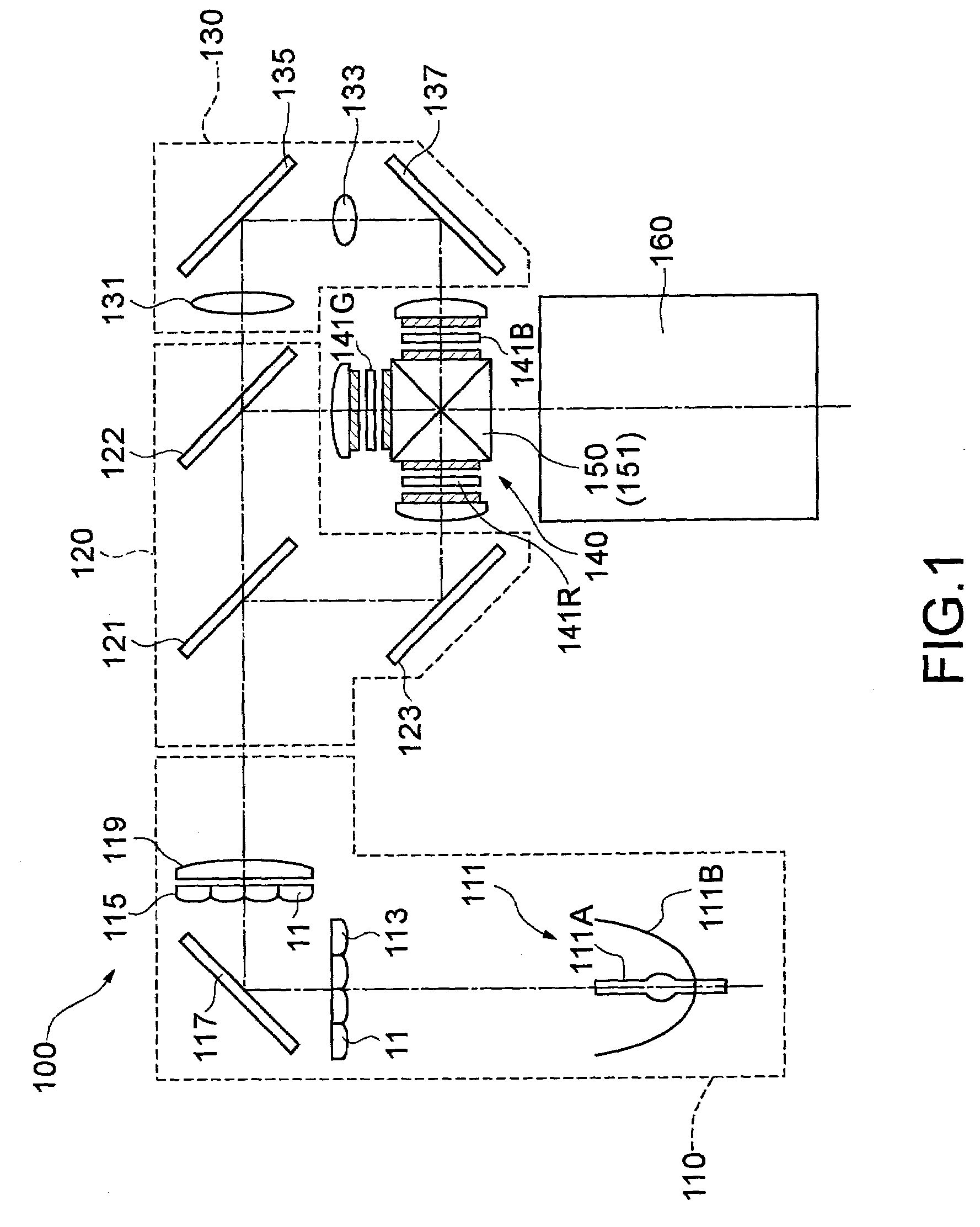
[0072]FIG. 1 is a schematic illustrating the structure of a projector 100 in which a lens array is adopted as an illumination optical device to be inspected by the device for inspecting an illumination optical device in accordance with a first embodiment of the present invention.

[0073]The projector 100 is equipped with an integrator illumination optical system 110, a color separating optical system 120, a relay optical system 130, an electro-optical device 140, a color synthesizing optical system 150, and a projection optical system 160.

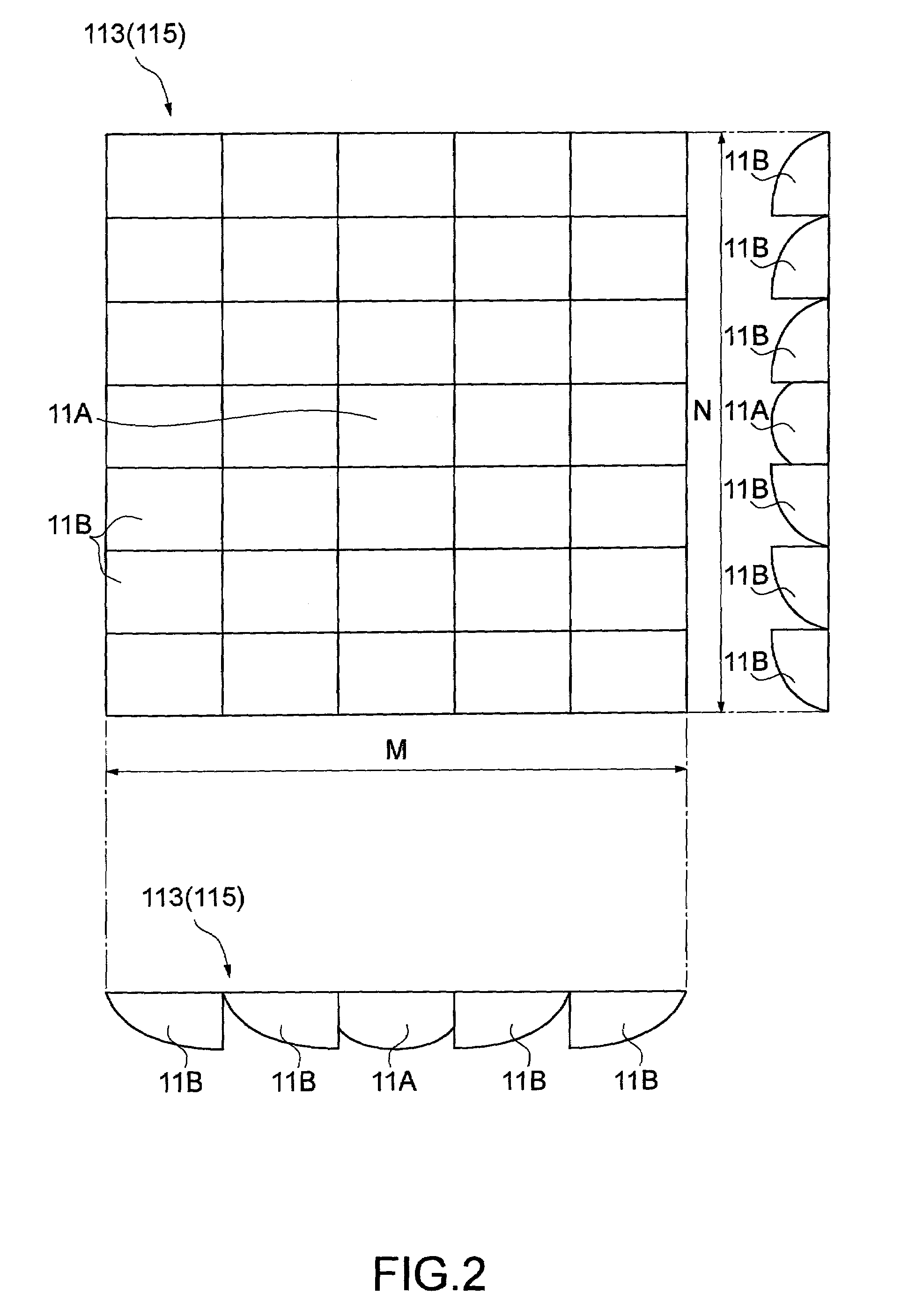
[0074]The integrator illumination optical system 110 is equipped with a light source device 111 including a light source lamp 111A and a reflector 111B, a first lens array 113, a second lens array 115, a reflection mirror 117, and a superimposing lens 119.

[0075]A luminous flux from the light source lamp 111A is emitted as a parallel luminous flux whose outgoing d...

second embodiment

[0161]A lens array inspecting device 3 according to a second embodiment of the present invention will now be explained. The lens array inspecting device 3 according to the second embodiment and the lens array inspecting device 2 according to the first embodiment differ in the automatic inspection method, namely, the method to determine pass / fail of the first lens array 113. Thus, an image processing device 410 is provided with a program that updates its configuration according to a change of the pass / fail determining method. The rest of the construction is the same as the construction of the first embodiment, and like or equivalent components as those of the first embodiment will be assigned like reference numerals and the explanation thereof will be omitted or simplified.

[0162]The image processing device 410 constituting the main unit 402 is equipped with the luminance determining unit 420 and the image display unit 430, as shown in FIG. 17. Referring also to FIG. 20, the image pro...


PUM

PropertyMeasurementUnit
aspect ratioaaaaaaaaaa
luminous fluxaaaaaaaaaa
opticalaaaaaaaaaa

Abstract

The invention provides a device to inspect an illumination optical device and a method to inspect an illumination optical device that make it possible to efficiently inspect illumination optical devices and to control manufacturing cost. A lens array inspecting device is provided with a light source device to emit a parallel luminous flux, lens array holders to retain lens arrays, which are test objects that split the parallel luminous flux into a plurality of partial luminous fluxes, and a ground glass on which the optical images of the luminous fluxes emitted through the lens arrays are projected. On the ground glass, a parting frame appropriate to a design illumination region is formed. Therefore, whether the lens arrays are defective or non-defective can be determined by checking whether the optical images projected onto the ground glass include the area of the parting frame.

Description

BACKGROUND OF THE INVENTION[0001]1. Field of Invention[0002]The present invention relates to a apparatus for inspecting an illumination optical device. In particular, the invention relates to an apparatus for inspecting the optical characteristics of an illumination optical device constituting an illumination optical system that condenses a luminous flux emitted from a light source lamp to form an optical image. The invention also relates to a method for inspecting a lens array serving as the illumination optical device.[0003]2. Description of Related Art[0004]Projectors can be used for presentations or the like. Projectors can be equipped with a light source lamp, an electro-optical device that modulates a luminous flux emitted from the light source lamp according to image information, and a projection optical system to enlarge and projecting the luminous flux modulated by the electro-optical device.[0005]In such a projector, an illumination optical system is frequently disposed be...

Claims


Application Information

Patent Timeline
Patent Type & Authority Patents(United States)
IPC IPC(8): G06K9/00G01B9/08G01N21/00H04N7/18H04N9/47G01N21/958G02B27/14
CPCG01N21/958G01N21/00
Inventor KITABAYASHI, MASASHI
Owner SEIKO EPSON CORP
Why Eureka
Try Eureka