Level 2 cache index hashing to avoid hot spots

a cache index and hot spot technology, applied in the direction of memory adressing/allocation/relocation, instruments, computing, etc., can solve the problems large percentage of time elapsed during pipeline stalling and idling, and the most detrimental effect of stalling and idling, so as to reduce or avoid conflicting memory accesses, reduce the probability of hot spots in the cache, and reduce the probability of address conflicts

Active Publication Date: 2007-10-30
ORACLE INT CORP
View PDF95 Cites 72 Cited by
  • Summary
  • Abstract
  • Description
  • Claims
  • Application Information

AI Technical Summary

Benefits of technology

[0010]Broadly speaking, the present invention is a method and system for mapping memory addresses to reduce or avoid conflicting memory accesses in memory systems such as cache memories. To reduce address conflicts, a memory address is randomized to map a first addressing scheme (e.g., the memory address) into a second addressing scheme (e.g., the physical address used to access a cache) by hashing a portion (such as an index) of the memory address. The mapping function may losslessly transform all or part of the memory address so that the underlying information may be recovered. In addition, the mapping function may randomly spread or distribute the memory address to reduce the probability of hot-spots in the cache. In a selected embodiment, a lookup table or one or more exclusive-OR gate circuits can be used to hash one or more bits in an index portion of a memory address to form a randomized cache index portion of the cache index.

Problems solved by technology

Because processor clock frequency is increasing more quickly than memory speeds, there is an ever increasing gap between processor speed and memory access speed.
In many commercial computing applications, this speed gap results in a large percentage of time elapsing during pipeline stalling and idling, rather than in productive execution, due to cache misses and latency in accessing external caches or external memory following the cache misses.
Stalling and idling are most detrimental, due to frequent cache misses, in database handling operations such as OLTP, DSS, data mining, financial forecasting, mechanical and electronic computer-aided design (MCAD / ECAD), web servers, data servers, and the like.
Thus, although a processor may execute at high speed, much time is wasted while idly awaiting data.
Processing applications, such as database applications and network computing applications, spend a significant portion of execution time stalled awaiting memory servicing.
Vertical multithreading imposes costs on a processor in resources used for saving and restoring thread states, and may involve replication of some processor resources, for example replication of architected registers, for each thread.
In addition, vertical multithreading complicates any ordering and coherency requirements for memory operations when multiple threads and / or multiple processors are vying for access to any shared memory resources.

Method used


Image

  • Level 2 cache index hashing to avoid hot spots
  • Level 2 cache index hashing to avoid hot spots
  • Level 2 cache index hashing to avoid hot spots

Examples


Embodiment Construction

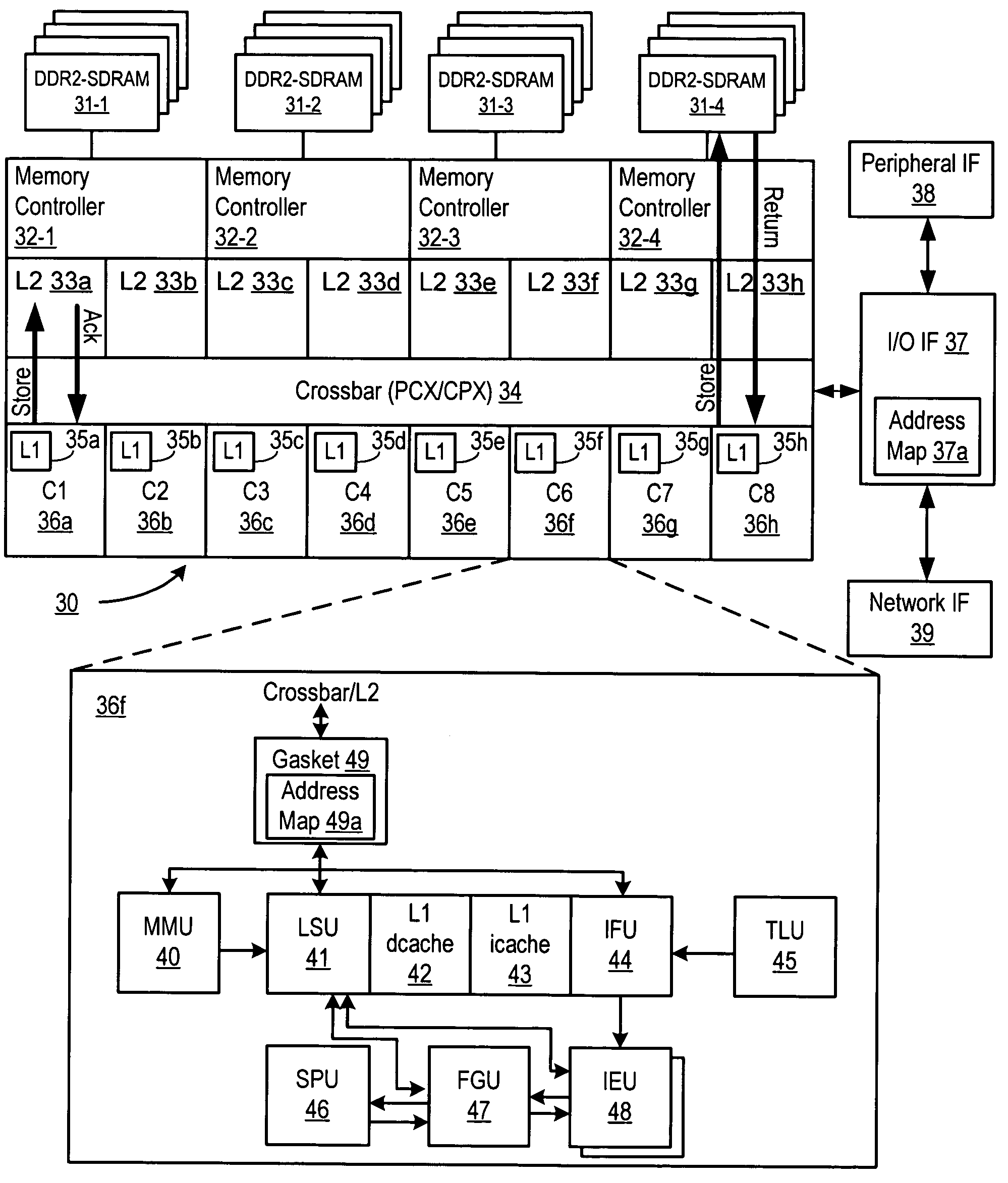
[0021]As explained herein, when multiple thread and / or processor operations are using a shared memory system, the memory operations must be coordinated so that each thread can access the memory in an ordered and coherent way with minimal delay or latency. For purposes of providing an exemplary and not limiting description, it will be useful to describe the various aspects and embodiments of the invention herein in the context of memory operations for an on-chip cache memory system that is constructed with CMOS SRAM memory cells. However, the present invention is not limited to CMOS-based processes and may be used in connection with other categories of memory products, including without limitation, DRAM, ROM, flash, PLA and the like, whether integrated within a VLSI system, cache or non-cache, or a stand alone memory device.

[0022]A selected embodiment of the present invention is shown in FIG. 3, which depicts a simplified schematic diagram of a processor chip 30 having multiple proce...


PUM


Abstract

An apparatus and method for mapping memory addresses to reduce or avoid conflicting memory accesses in memory systems such as cache memories is described in connection with a multithreaded multiprocessor chip. A CMT processor reduces the probability of hot-spots in cache operations by hashing certain bits of a physical cache address to form a hashed cache address. By using exclusive OR functionality to hash the index bits, an efficient address transformation is achieved for indexing into an L2 cache memory.

Description

BACKGROUND OF THE INVENTION[0001]1. Field of the Invention[0002]The present invention relates generally to the field of processor or computer design and operation. In one aspect, the present invention relates to memory operations in a multi-threaded processor.[0003]2. Description of the Related Art[0004]Computer systems are constructed of many components, typically including one or more processors that are connected for access to one or more memory devices (such as RAM) and secondary storage devices (such as hard disks and optical discs). For example, FIG. 1 is a diagram illustrating a computer system 10 with multiple memories. Generally, a processor 1 connects to a system bus 12. Also connected to the system bus 12 is a memory (e.g., 14). During processor operation, CPU 2 processes instructions and performs calculations. Data for the CPU operation is stored in and retrieved from memory using a memory controller 8 and cache memory, which holds recently or frequently used data or ins...

Claims


Application Information

Patent Timeline
Patent Type & Authority Patents(United States)
IPC IPC(8): G06F12/00
CPCG06F12/0864G06F12/0811
Inventor GROHOSKI, GREG F.SHAH, MANISHDAVIS, JOHN D.SAULSBURY, ASHLEYFU, CONGIYENGAR, VENKATESHTSAI, JENN-YUANGIBSON, JEFF
Owner ORACLE INT CORP
Why Eureka
Try Eureka