
Separation membrane module with hollow fiber and a method of making the same

Inactive Publication Date: 2007-11-06
GORE ENTERPRISE HLDG INC
View PDF17 Cites 10 Cited by
  • Summary
  • Abstract
  • Description
  • Claims
  • Application Information

AI Technical Summary

Benefits of technology

[0012]The object of the present invention is to provide a separation membrane module having hollow fibers at a high hollow fiber packing rate, in which there is a very good seal in the sealed parts of the hollow fibers, in which excellent airtightness can be guaranteed without the presence of air bubbles or the like, and in which there is no need to use a resin for sealing the hollow fibers together.

Problems solved by technology

However, the sealant resins are inadequate in terms of heat resistance and chemical resistance.
Therefore, their use is limited to applications in which acid- or alkali-containing solutions or organic solvents are used as the media or liquid detergents, or to applications in which steam sterilization is performed.
On the other hand, when a thermofusible resin is used as a sealant for hollow fibers, it is difficult to penetrate fine voids, such as those between the outer cylinder and hollow fiber bundles or between the hollow fiber bundles, if the viscosity of the thermofusible resin is high.
Moreover, it is difficult to defoam high-viscosity resins once air bubbles have formed, and inadequate sealing sometimes results.
Methods have also been proposed in which an outer cylinder with through-holes in the form of a beehive (that is, a honeycomb) is preformed from a resin, and hollow fibers are then inserted into the through-holes and melted by heat, but it is difficult in itself to form a large number of through-holes at a high density in the outer cylinder, and it is difficult to completely seal the voids.
Consequently, it is impossible to finely mold sealed parts using a thermofusible resin, and neither is it possible to raise the hollow fiber packing rate by these methods.

Method used


Image

  • Separation membrane module with hollow fiber and a method of making the same
  • Separation membrane module with hollow fiber and a method of making the same
  • Separation membrane module with hollow fiber and a method of making the same

Examples


example 1

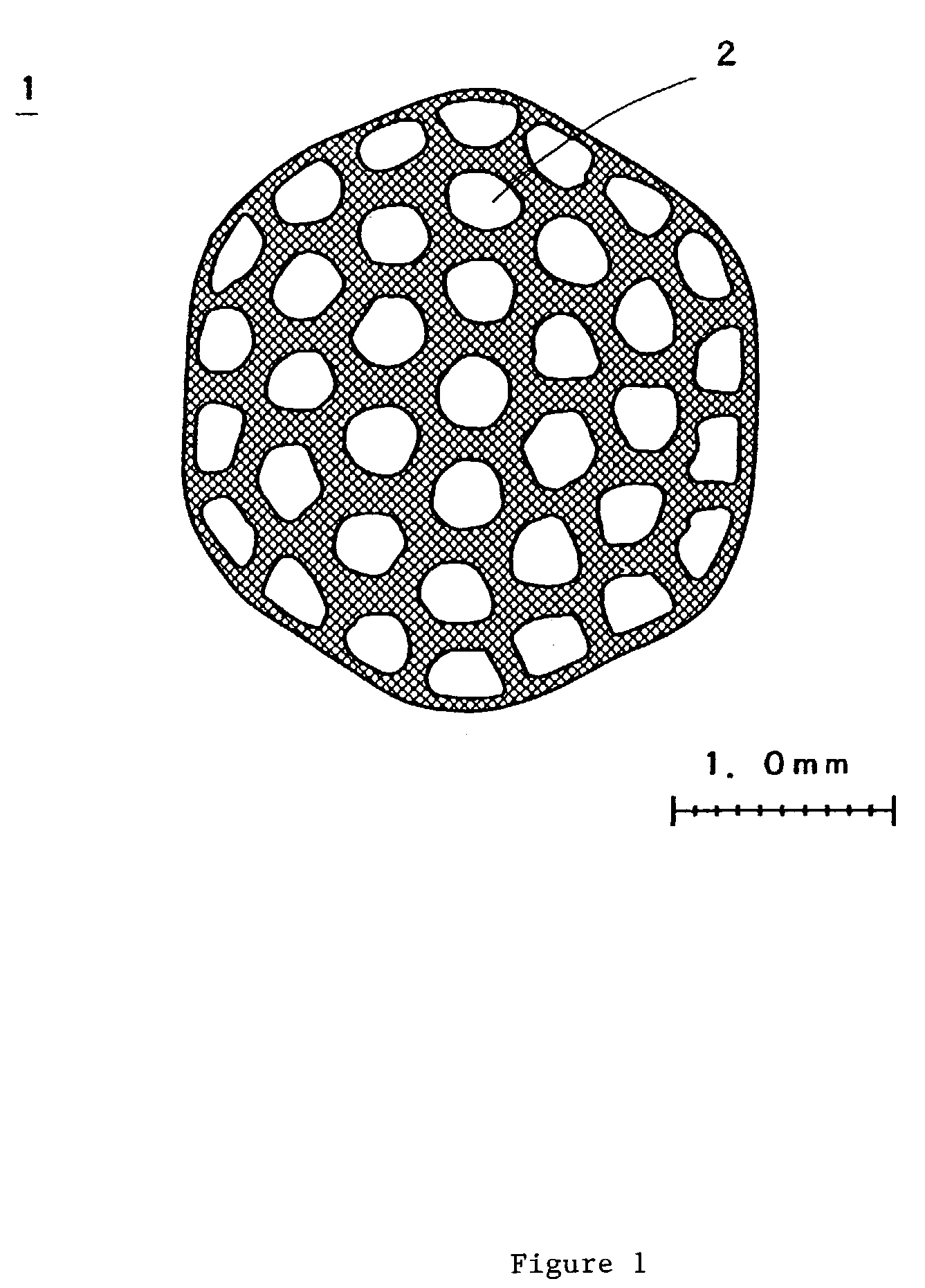
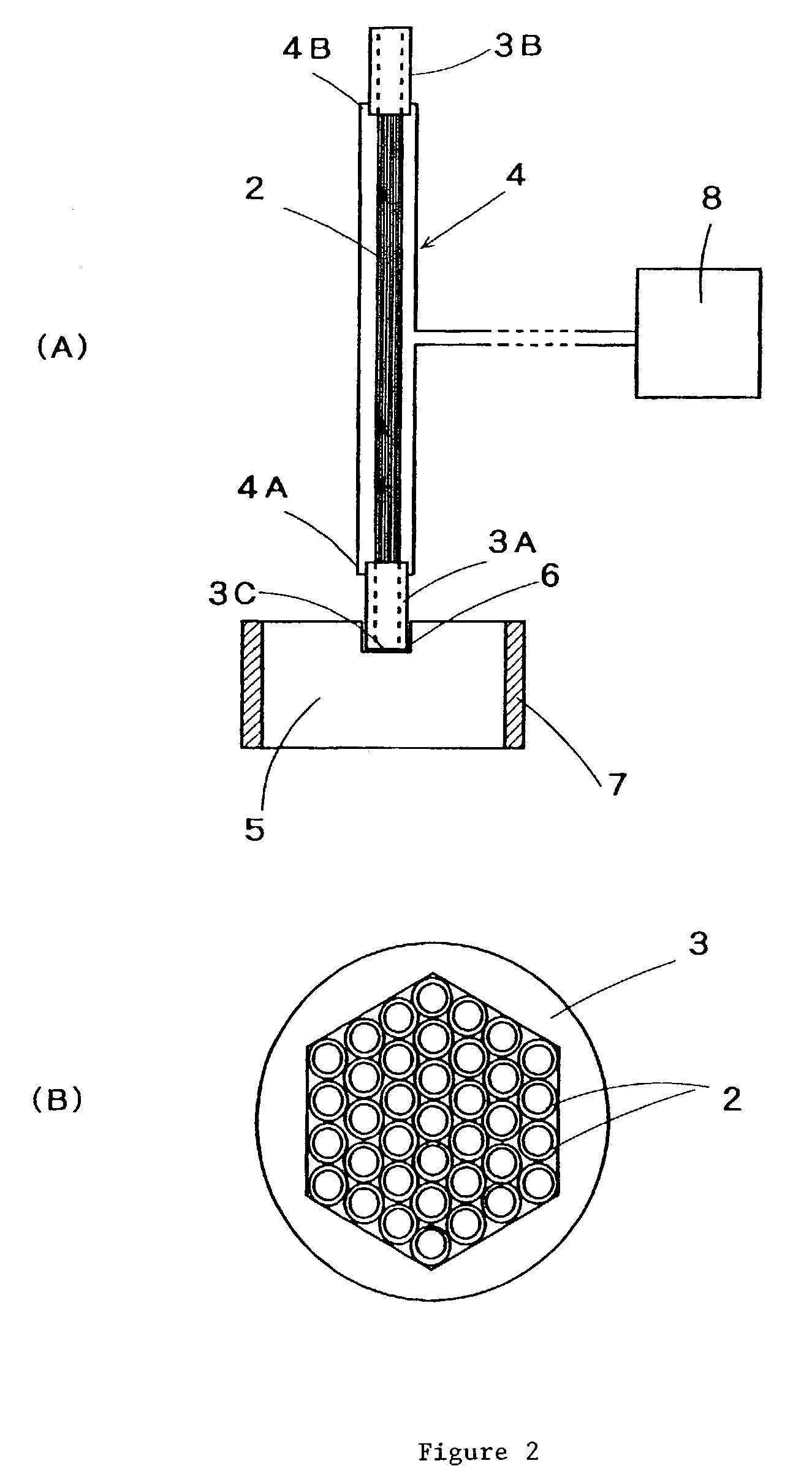
[0068]Both ends of 37 hollow fiber of amorphous fluororesin copolymer (DuPont, Teflon AF1600) with a diameter of 0.6 mm, inner diameter of 0.45 mm, thickness of 0.075 mm, and length of 100 mm were inserted into a polytetrafluoroethylene sheath with a regular hexagonal opening. The sheath was kept for 15 minutes inside a mold that had been heated to 240° C., with the spaces inside the sheath being joined to and decompressed with a polytetrafluoroethylene tube for decompression. The surfaces of the hollow fibers inside the sheath were integrally fused, and the sheath was then removed from the mold and cooled. After the yarns at one end were fused and integrated, the yarns at the other end were similarly fused and integrated.

[0069]Next, two cap screws made of polytetrafluoroethylene were driven into both ends of the integrally fused hollow fibers, and a regular hexagonal opening capable of accommodating the external shape of integrally fused hollow fibers was formed on the inside of a ...


PUM

PropertyMeasurementUnit
Temperatureaaaaaaaaaa

Abstract

A separation membrane module having hollow fibers, wherein a plurality of hollow fibers are heated and melted to bond and thermally fuse the external surfaces of the hollow fibers with each other; and a method of manufacturing a separation membrane module having hollow fibers whereby the ends of a plurality of hollow fibers are inserted into a sheath, the sheath and the hollow fibers are tightly bonded together to form spaces, and the sheath portion into which hollow fibers have been inserted is heated up to the temperature at which the surfaces of the hollow fibers melt, with the spaces thus formed kept in a decompressed state, so that the exterior surfaces of the hollow fibers are thermally fused and integrated together.

Description

BACKGROUND OF THE INVENTION[0001]1. Field of the Invention[0002]The present invention relates to a separation membrane module provided with a large number of hollow fibers, and in particular to a separation membrane module having hollow fibers that is used for the purpose of gas separation, degassing, dissolution of gases in liquids, and the like, and that has a large number of hollow fibers in which a thermofusible synthetic resin is provided at least on the surfaces thereof; and to a manufacturing method thereof.[0003]2. Description of Related Art[0004]Separation membrane modules that use hollow fibers have an increased membrane surface area per unit volume, and are therefore used as modules having a large number of porous separation membranes in the form of hollow fibers.[0005]The vacant spaces between the hollow-fiber separation membranes, and the voids between the hollow-fiber separation membranes and the outer cylinder for housing these membranes, are sealed by a sealant or th...

Claims


Application Information

Patent Timeline
IPC IPC(8): B01D53/22B01D19/00B01D61/00B01D63/00B01D63/02B01D71/32B29C65/02
CPCB01D63/021B01D63/022B01D63/023B01D71/32B29C66/5344B29C65/18B29C66/5227B29L2031/14B29L2031/602B29C66/8322B29C66/73921B29C66/73772B29C66/71B29C66/112B29C66/1122B29C66/131B29K2027/18B29K2027/12B01D63/0233B01D63/0223
Inventor SUZUKI, MASAHIRONAGANUMA, TSUNEHIKO
Owner GORE ENTERPRISE HLDG INC
Learn More