Operating method for a wind turbine with a supersynchronous cascade

a supersynchronous cascade and wind turbine technology, applied in the direction of variable speed operation control, electric generator control, dynamo-electric converter control, etc., can solve the problems of increasing the difficulty of equalizing short-term power variations in utilities, increasing the difficulty of increasing the difficulty of short-term power variations, and increasing the need for reactive power, so as to improve the current quality and ensure the effect of efficient production of electric energy

a supersynchronous cascade and wind turbine technology, applied in the direction of variable speed operation control, electric generator control, dynamo-electric converter control, etc., can solve the problems of increasing the difficulty of equalizing short-term power variations in utilities, increasing the difficulty of increasing the difficulty of short-term power variations, and increasing the need for reactive power, so as to improve the current quality and ensure the effect of efficient production of electric energy

US7291937B2Inactive Publication Date: 2007-11-06DEWIND TURBINE CO

Image

  • Operating method for a wind turbine with a supersynchronous cascade
  • Operating method for a wind turbine with a supersynchronous cascade
  • Operating method for a wind turbine with a supersynchronous cascade

Examples


Embodiment Construction

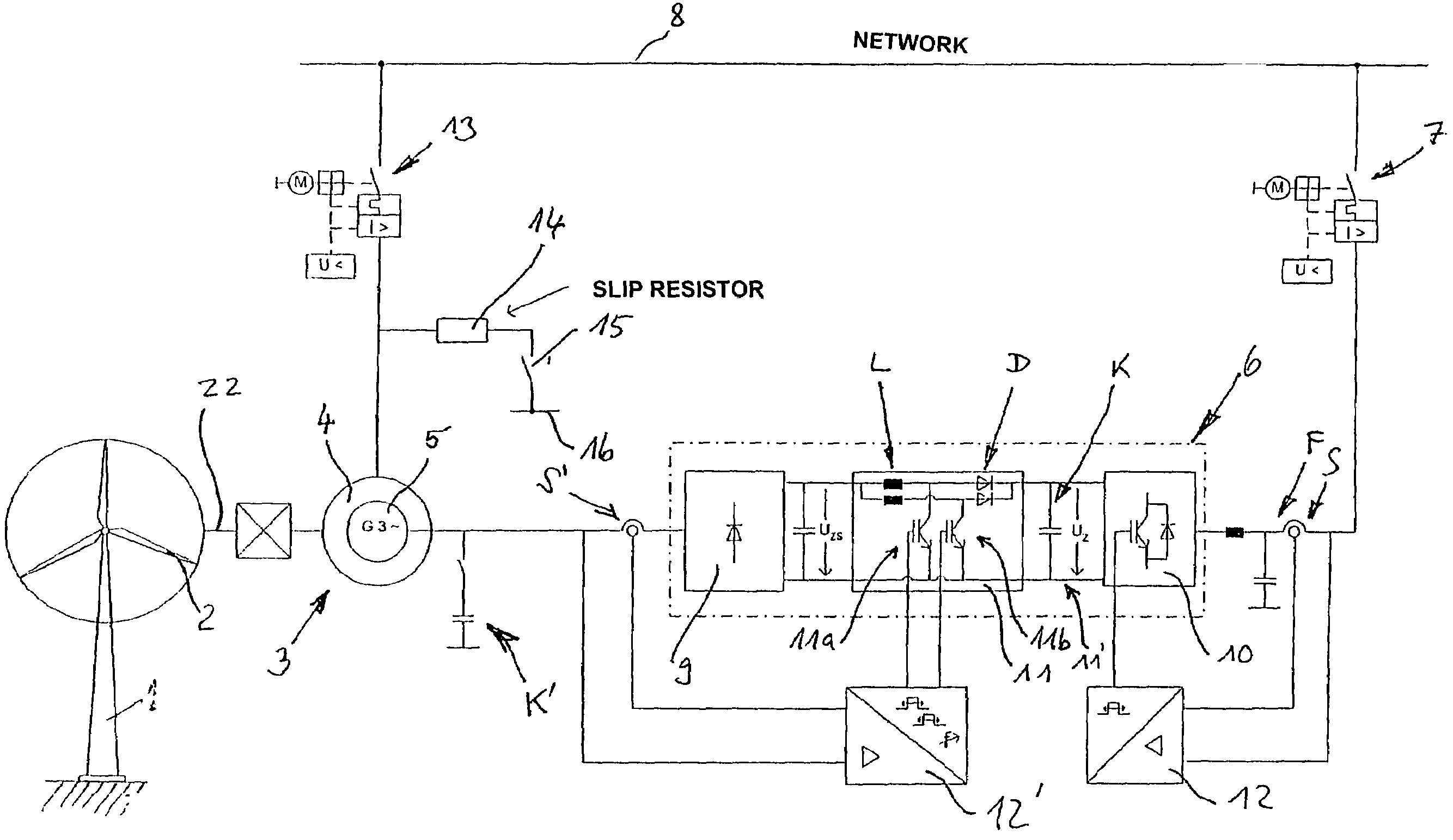
[0033]The wind energy system according to the invention that is shown has a mast 1 that is anchored in the ground and a rotor 2 having three rotor blades that are mounted at the top of the mast 1. The rotor blade angles are configured to be adjustable relative to their longitudinal axis. The rotor 2 is mechanically connected with an electric asynchronous generator 3, by way of a gear mechanism. The stator 4 of the generator 3 is electrically connected with the network 8. In this connection, the network frequency and the frequency generated in the stator are synchronized with one another. The rotor 5 of the generator 3 is connected with the converter array 6 by way of the lines, which array in turn is connected with the lines between the stator 4 and the network 8. The slip power generated by the generator is fed into the network with the converter array 6. The slip power of the rotor and therefore the speed of rotation are controlled variably. The power to be fed into the network 8 ...


PUM


Abstract

The invention relates to a wind energy system having a rotor that can be driven by the wind, preferably having one or more rotor blades that can be adjusted in angle, a generator directly or indirectly connected with the rotor, to generate electric energy, which is configured as an asynchronous generator having a super-synchronous converter cascade in the rotor circuit, for slip-variable generator operation, so that power output of the generator is possible at variable speeds of rotation of the rotor, and an operation guide system that is configured to regulate the speed of rotation of the rotor, within a predetermined wind speed range. To improve the energy yield, it is provided that the super-synchronous rectifier cascade is configured in the rotor circuit for feeding the slip power into the network. For this purpose, the super-synchronous converter cascade has a DC voltage intermediate circuit having a high-set element. These are configured to switch, as IGBT switches, with a 180 degree phase shift relative to the rotor voltage.Furthermore, the invention relates to a method for regulating the power output of the wind energy system, in that the slip is regulated, whereby the slip power is fed into the network.

Description

CROSS REFERENCE TO RELATED APPLICATIONS[0001]Applicants claim priority under 35 U.S.C. 365 of PCT / EP2002 / 010116 filed on Sep. 10, 2002. The international application under PCT article 21(2) was not published in English.BACKGROUND OF THE INVENTION[0002]1. Field of the Invention[0003]The invention relates to a wind energy system having a rotor that can be driven by the wind, preferably having one or more rotor blades that can be adjusted in angle, a generator directly or indirectly connected with the rotor, to generate electric energy, which is configured as an asynchronous generator having a super-synchronous converter cascade in the rotor circuit, for slip-variable generator operation ,so that power output of the generator is possible at different speeds of rotation of the rotor, and an operation guide system that is configured to regulate the speed of rotation of the rotor, within a predetermined wind speed range, preferably with adjustment of the rotor blade angles.[0004]Furthermo...

Claims


Application Information

Patent Timeline
06 Nov 2007
Publication
US7291937B2
IPC
H02P9/00; F03D7/04; F03D9/00; H02J3/38
CPC
F03D9/003; H02J3/386; H02P9/007; F05B2260/74; F05B2270/1016; H02P2101/15; Y02E10/72; Y02E10/763
Inventors
WILLISCH, WOLF; MULLER, ROBERT