Pressure sensitive switches including touch sensor structures

a technology of touch sensor and pressure sensitive switches, which is applied in the direction of switch power arrangements, emergency protective arrangements for limiting excess voltage/current, contact mechanisms, etc., can solve the problems of battery exhaustion, increased likelihood of flashlight mishandling, and increased risk of battery leakage and electrolyte corrosion, so as to reduce the likelihood of flashlight being mishandled, the effect of less cost and more reliabl

Inactive Publication Date: 2007-11-06
GLOBAL TOUCH SOLUTIONS +1
View PDF3 Cites 44 Cited by
  • Summary
  • Abstract
  • Description
  • Claims
  • Application Information

AI Technical Summary

Benefits of technology

[0018]According to one embodiment of the present invention, there is provided a microchip controlled switch to manage both the current conducting functions and the MMI functions in an electronic device, such as a flashlight, on a low current basis i.e. without the MMI device having to conduct or switch high current. According to one aspect of the invention, the MMI functions are controlled by very low current signals, using touch pads, or carbon coated membrane type switches. These low current signal switches of the present invention can be smaller, more reliable, less costly, easier to seal and less vulnerable to the effects of corrosion and oxidation. Moreover, since the switch is a solid state component, it is, according to the present invention, possible to control the functions of the device in an intelligent manner by the same microchip which provides the MMI functions. Thus, by practicing the teachings of the present invention, more reliable, intelligent, and efficient electrical devices can be obtained which are cheaper and easier to manufacture than prior art devices.
[0019]According to another embodiment of the invention, there is provided a microchip which can be embedded in a battery that will lend intelligence to the battery and thus, the device it is inserted into, so that many functions, including but not limited to, delayed switching, dimming, automatic shut off, and intermittent activation may be inexpensively realized in an existing (non intelligent) product, for example a prior art flashlight.
[0020]According to a further embodiment, the invention provides a power saving microchip which, when operatively associated with an electronic device, will adjust the average electric current through a current switch, provide an on and off sequence which, for example, but not limited to, in the case of a flashlight, can be determined by an operator and may represent either a flash code sequence or a simple on / off oscillation, provide an indication of battery strength, and / or provide a gradual oscillating current flow to lengthen the life of the operating switch and the power source.
[0025]According to a still further embodiment of the invention, there is provided a microchip adapted to control lighting in buildings. According to this embodiment, the normal switch on the wall that currently functions as both a power-switch, i.e. conduction of electricity, and MMI can be eliminated, thus eliminating the normal high voltage and high current dangerous wiring to the switch and from the switch to the load or light. Utilizing the present invention, these switches can be replaced with connecting means suitable for low current DC requirements.

Problems solved by technology

Should the operator, after using the flashlight to find his / her way in the dark or for any other purpose, then fail to turn it off, the batteries will, in a very short time, become exhausted.
Should the flashlight be left in a turned-on and exhausted condition for a prolonged period, the batteries may then leak and exude corrosive electrolyte that is damaging to the contact which engages the battery terminal as well as the casing of the flashlight.
When the flashlight is designed for use by a young child the likelihood is greater that the flashlight will be mishandled, because a young child is prone to be careless and forgets to turn the flashlight “off” after it has served its purpose.
Because of this, a flashlight may be left “on” for days, if not weeks, and as a result of internal corrosion may no longer be in working order when the exhausted batteries are replaced.
It is difficult for a young child who wishes, say to illuminate a dark corner in the basement of his home for about 30 seconds, to keep a push button depressed for this period.
Over time, the switch suffers “wear and tear” which impairs operation of the flashlight as a result of, for example, repeated activations by the operator and / or due to the fact that the switch has been left “on” for a prolonged period of time.
In addition, such mechanical switches are vulnerable to the effects of corrosion and oxidation and can cause said switches to deteriorate and to become non-functioning.
In addition, these prior art devices having these mechanical switches are generally “dumb,” i.e. they do not provide the user with convenient, reliable, and affordable functionalities which today's consumers now demand and expect.
Depending upon the type of bulb and wiring employed, the intensity of electrical current which must be conducted by the switch is generally quite high leading to, after prolonged use, failure.
Second, these mechanical switches must function as an interface between the device and its operator, i.e. the man-machine-interface (“MMI”) and necessarily requires repeated mechanical activations of the switch which over time mechanically deteriorate.
These prior art switches suffer from the same disadvantages as the switches described above in relation to portable electronic devices, like flashlights.
Moreover, the switches are relatively dumb in most cases and do not provide the user with a variety of functions, e.g. but not limited to timing means to enable a user, for example, a shop owner or home owner to designate a predetermined shut off or turn on point in time.

Method used


Image

  • Pressure sensitive switches including touch sensor structures
  • Pressure sensitive switches including touch sensor structures
  • Pressure sensitive switches including touch sensor structures

Examples


Embodiment Construction

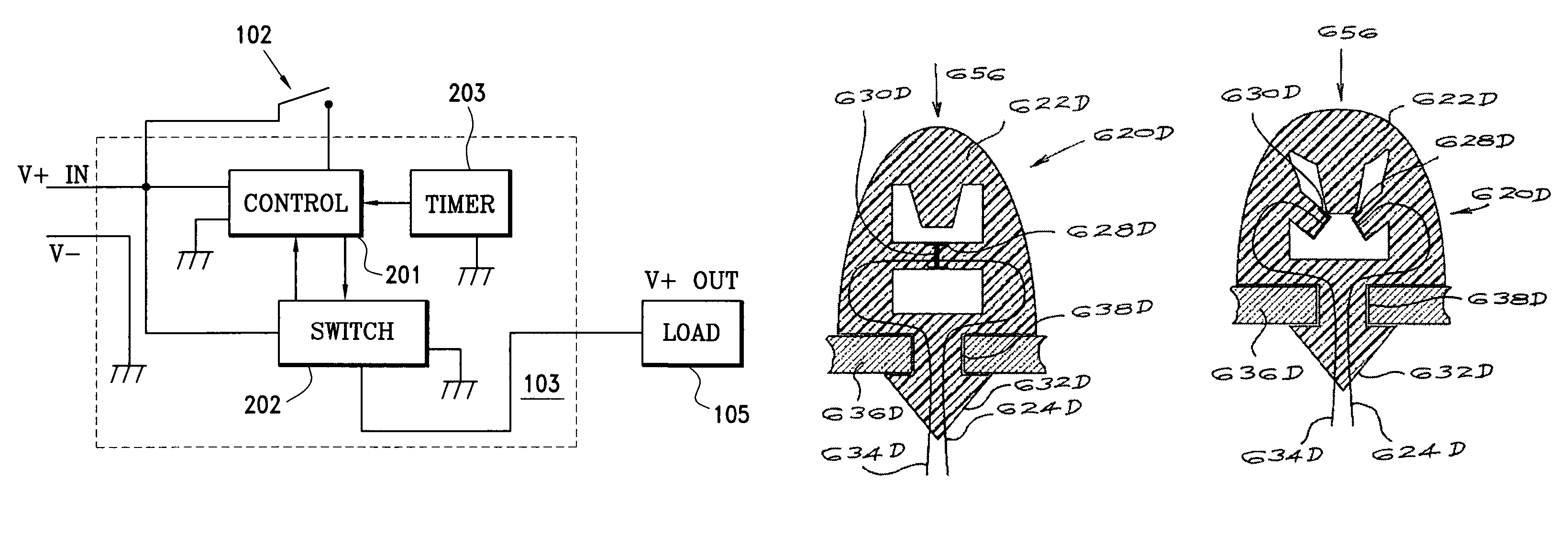
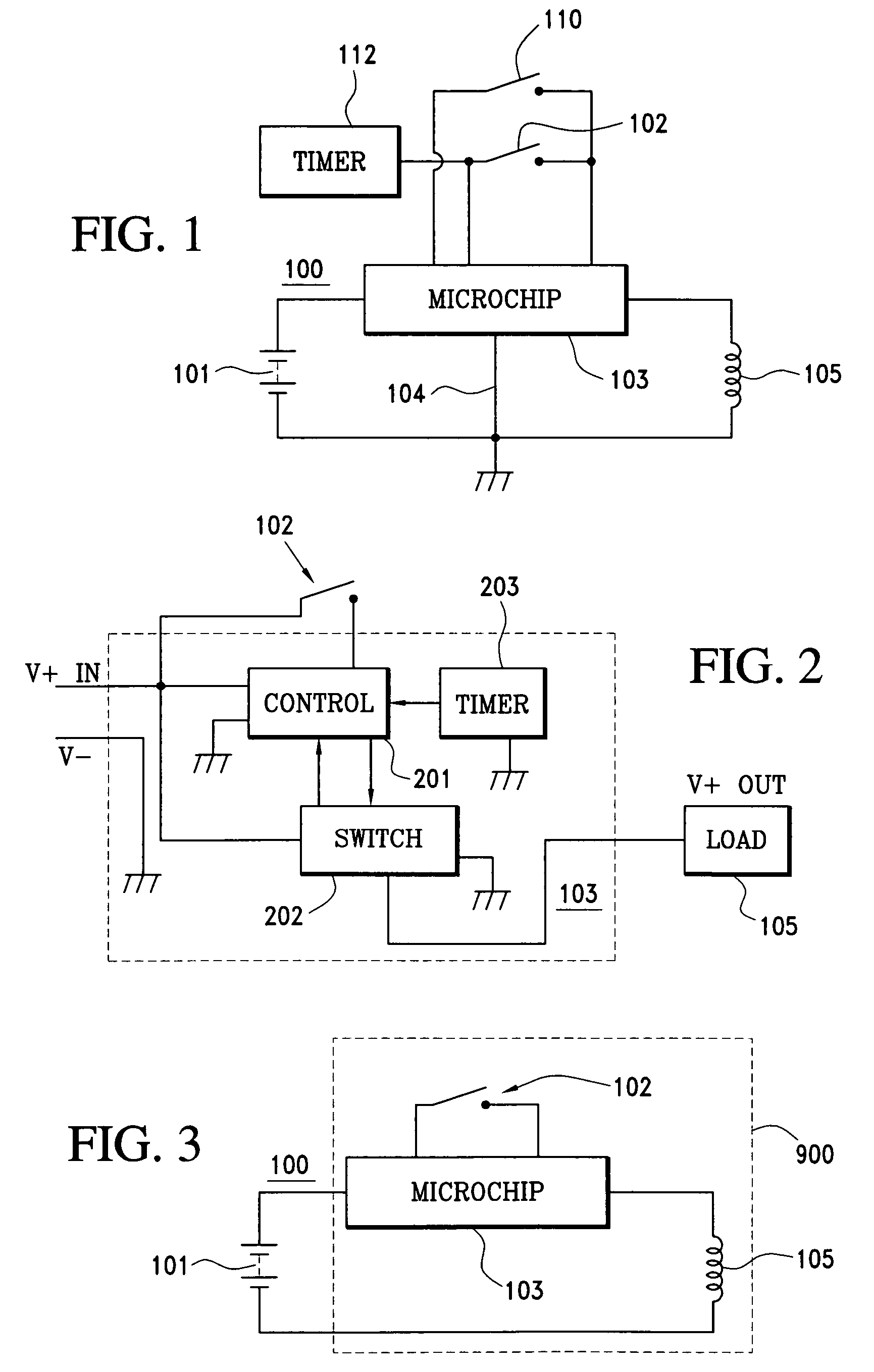
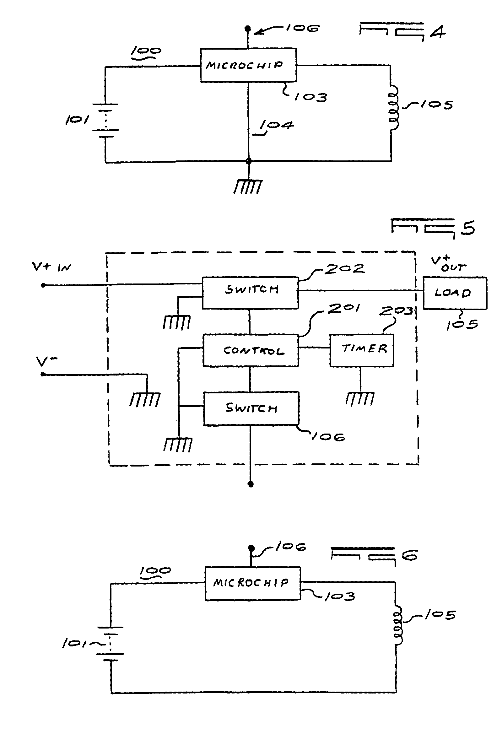
[0055]According to one embodiment or aspect of the present invention, and referring to FIG. 1, a schematic depiction of main circuit 100 of an electronic device, for example, a flashlight, is provided, wherein the device has a microchip 103 and a microchip controlled input activator / deactivator 102, for example, a push button or sliding switch. Main circuit 100 of the device is powered by a current supplied by power source 101. Power source 101 may be any power source, e.g. a DC battery, as is well known to those of ordinary skill in the art. While the following discussion is limited to specific electronic devices, that is flashlights, it is to be understood that the following description is equally applicable to other electronic devices including portable radios, toys, for example but not limited to battery operated cars, boats, planes, and / or other electrically powered toys.

[0056]Referring to FIG. 1, when an operator activates input push button or sliding command switch 102 to the...


PUM


Abstract

An electronic circuit for use with an exhaustible power source and at least one load such as a light bulb, a radio or motor, includes a microchip with an input that transmits a signal to the microchip when the load is activated or deactivated. The input does not form a serial link between the power source and the load. The power switch, by on / off switching, controls energy flow from the power source to the load. The input to the microchip acts as an activation / deactivation user interface. The microchip allows the user to select a specific load, specific functions for the selected load based on the time duration of activation signals, the time duration between activation signals and the number of activation signals at the input.

Description

CROSS REFERENCE TO RELATED APPLICATIONS[0001]This application is a Continuation-in-Part of U.S. application Ser. No. 09 / 806,860, filed Jul. 2, 2001 now U.S. Pat. No. 6,984,900, which is a U.S. National Stage of International Application No. PCT / ZA99 / 00107, filed Oct. 8, 1999, which is a Continuation-in-Part of U.S. application Ser. No. 09 / 169,395, filed Oct. 9, 1998, now U.S. Pat. No. 6,249,089.FIELD OF THE INVENTION[0002]The present invention relates to new intelligent electrical current switching devices and more particularly, to microchip controlled electrical current switching devices. The invention further relates, in one embodiment, to intelligent batteries having embedded therein a microchip for use with a variety of electrical devices to add heretofore unknown functionality to existing electrical devices. The invention also relates, according to another embodiment, to intelligent hand-held electronic devices, and in a preferred embodiment to hand-held light sources, and more...

Claims


Application Information

Patent Timeline
Patent Type & Authority Patents(United States)
IPC IPC(8): H01H3/26H02H3/00H05B37/02H05B39/04
CPCH01H13/063H05B37/02H05B37/0245H05B39/041H05B39/044H05B37/0281Y02B20/48Y02B20/42H05B47/16H05B47/165H05B47/17H05B47/175H05B47/185Y02B20/00Y02B20/40
Inventor BRUWER, FREDERICK JOHANNES
Owner GLOBAL TOUCH SOLUTIONS
Why Eureka
Try Eureka