
High-frequency power source

a power source and high-frequency technology, applied in the field of high-frequency power sources, can solve the problems of high maintenance cost, inability to meet the needs of high-frequency power supply, etc., to achieve the effect of reducing the minimum value and avoiding the effect of fluctuation

Inactive Publication Date: 2007-11-06
DAIHEN CORP
View PDF4 Cites 19 Cited by
  • Summary
  • Abstract
  • Description
  • Claims
  • Application Information

AI Technical Summary

Benefits of technology

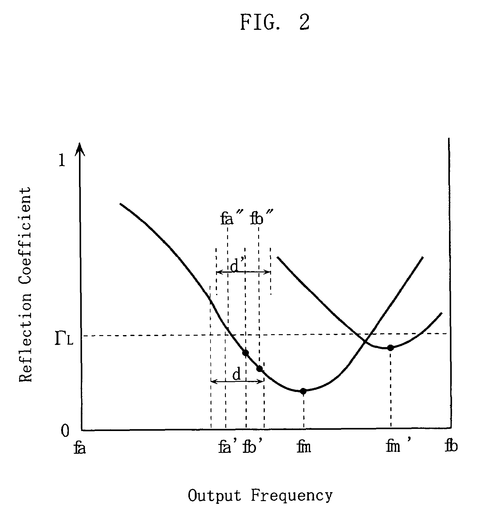
[0015]With the above constitution, the load has a reflection characteristic that high-frequency power supplied at an output frequency is reflected at a rate which fluctuates with time. For this load, there is obtained an output frequency at which the reflection coefficient takes a minimum value, within a preset frequency range. Then, high-frequency power of the obtained output frequency is supplied to the load. Therefore, it is possible to obtain an output frequency at which the reflection coefficient takes a minimum value more quickly than other methods such as a scanning method in which scanning is made constantly to output frequencies, and measurement is made for a reflection coefficient at each scanned output frequency, to obtain the smallest reflection coefficient from the measured reflection coefficients and then a corresponding output frequency to the smallest reflection coefficient. Furthermore, with a minimum value of the reflection coefficient fluctuating with time in the load, the present invention enables to follow the fluctuation quickly.

Problems solved by technology

There is a problem, however, that it takes time, e.g. one second or so, for the impedance-matching unit 32 to complete the impedance matching operation.
Due to the moving parts of the motors, the impedance-matching unit 32 does not have a high level of maintainability and also is susceptible to breakdown.
As another problem, the impedance-matching unit 32 is costly.

Method used


Image

  • High-frequency power source
  • High-frequency power source
  • High-frequency power source

Examples


Embodiment Construction

[0034]Preferred embodiments of the present invention will now be described below with reference to the accompanying drawings.

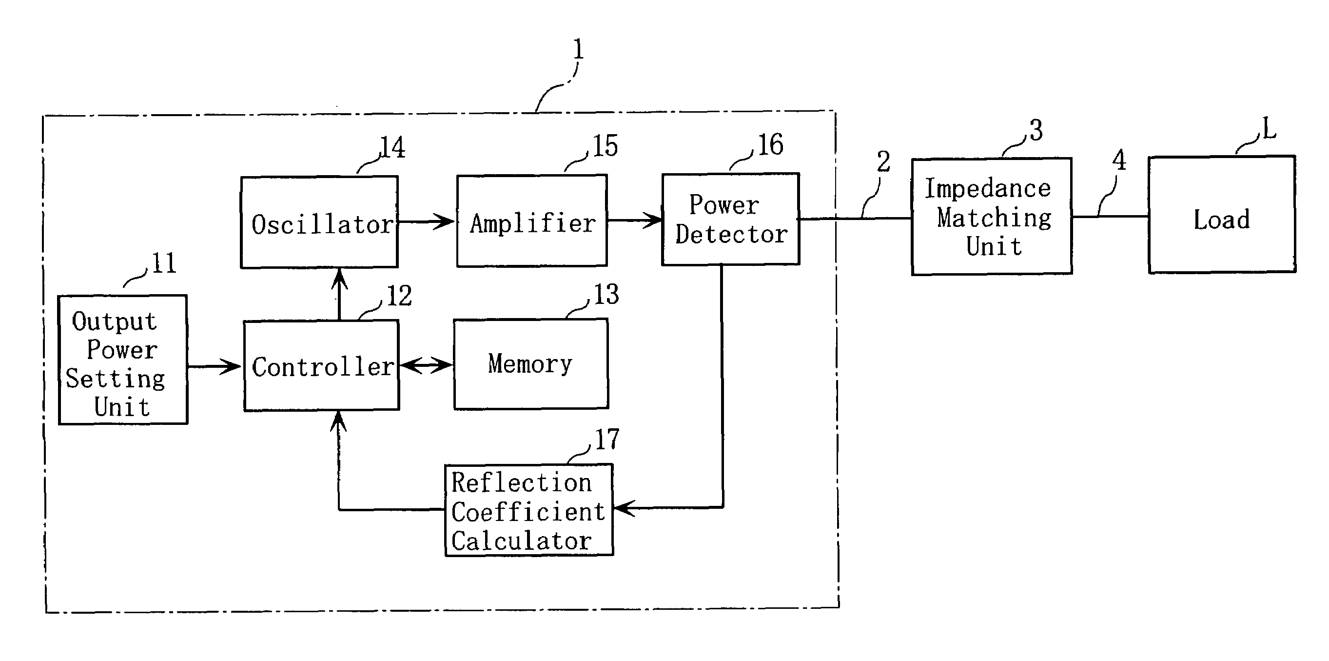
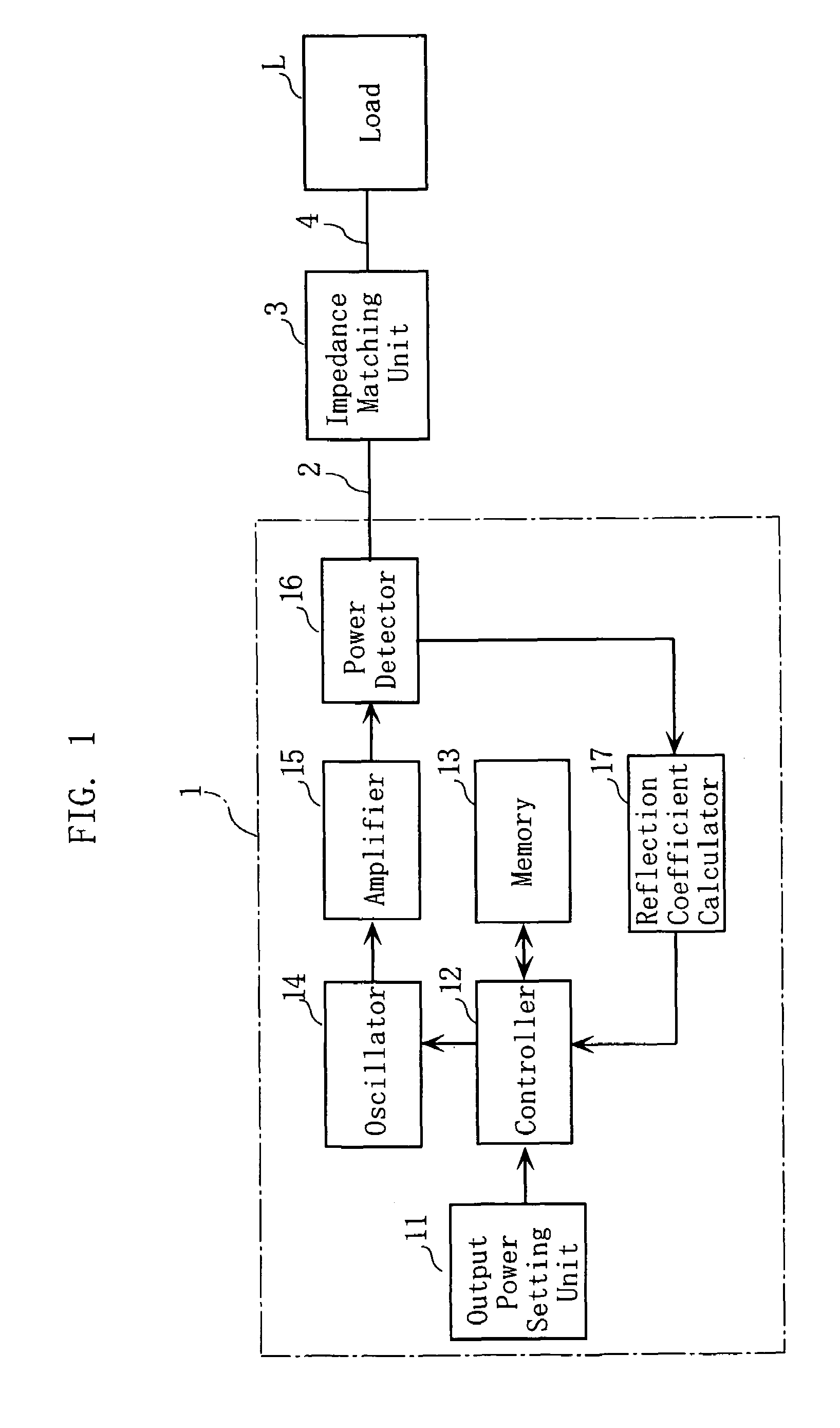
[0035]FIG. 1 shows a high-frequency power supply system embodying a high frequency power source according to the present invention. The high-frequency power supply system supplies high-frequency power necessary for performing the processing (e.g. plasma etching) of works such as semiconductor wafers and liquid crystal substrates. The high-frequency power supply system includes a high-frequency power source 1, a transmission line 2, an impedance-matching unit 3, a load connecting section 4 and a load L.

[0036]The high-frequency power source 1 is connected with the impedance-matching unit 3 via the transmission line 2 which may be a coaxial cable, for example. The impedance-matching unit 3 is connected with the load connecting section 4, which may be a copper plate properly shielded for preventing leakage of electromagnetic waves. The load connecting section 4 is...


PUM


Abstract

A high-frequency power source supplies high-frequency power to a load whose reflection characteristic for the power varies with time. The power source includes a frequency-variable power generator, a power detector for detecting the power into the load and the power from the load, a reflection coefficient calculator for calculating a reflection coefficient based on the detection of the power into and from the load, a frequency detector causing the power generator to generate high-frequency powers at various frequencies within a predetermined frequency range for obtaining the frequency that gives a minimum value to the calculated reflection coefficient, and a power supply controller for causing the power generator to generate a high-frequency power of the frequency obtained by the frequency detector and for supplying the high-frequency power to the load.

Description

BACKGROUND OF THE INVENTION[0001]1. Field of the Invention[0002]The present invention relates to a high-frequency power source that supplies high-frequency electric power to a load such as a plasma processor for performing plasma etching in e.g. semiconductor wafer processing.[0003]2. Description of the Related Art[0004]FIG. 11 illustrates a conventional high-frequency power supply system disclosed in JP-A-H05-63604. The high-frequency power supply system includes a high-frequency power source 31 for outputting high-frequency power, and an impedance-matching unit 32, connected with the high-frequency power source 31 via e.g. a coaxial cable, for matching the input impedance of the high-frequency power source 31 with the load impedance. Further, the power supply system includes a load connecting section 33 and a load L. The connecting section 33, provided by e.g. a copper plate, is connected with the impedance-matching unit 32. The load L, e.g. a plasma processor, is connected with t...

Claims


Application Information

Patent Timeline
Patent Type & Authority Patents(United States)
IPC IPC(8): G01R27/00
CPCH01J37/32082H01J37/32174H05H1/46H01J37/32935H03H7/40
Inventor TANAKA, RYOHEIMATOBA, HIROSHI
Owner DAIHEN CORP
Learn More