Power amplifier efficiency

a technology of power amplifier and efficiency, applied in the direction of transmission monitoring, sustainable buildings, modulation, etc., can solve the problems of increasing the power consumption of the terminal, difficult to improve the capacity of the battery, and the output of less than maximal power will not work optimally efficient, so as to improve the efficiency of the transmitting radio frequency and reduce the power consumption of the portable radio communication devi

Active Publication Date: 2007-11-06
SAMSUNG ELECTRONICS CO LTD
View PDF14 Cites 2 Cited by
  • Summary
  • Abstract
  • Description
  • Claims
  • Application Information

AI Technical Summary

Benefits of technology

[0009]An object of the present invention is to provide a method and an arrangement that reduce the power consumption of a portable radio communication device by improving the efficiency of the transmitting radio frequency (TX-RF) front end thereof.
[0010]Another object of the present invention is to avoid the problem of matching components in a portable radio communication device to the standard of 50 Ohms.
[0013]By providing in a portable radio communication device, such as a mobile phone, an antenna element having a variable antenna radiating impedance, it is possible to provide a load loading the power amplifier so that the power amplifier operates as efficiently as possible for any desired transmission power output.

Problems solved by technology

New mobile communication systems are continuously being developed and more and more functions tend to be integrated into the mobile phone terminals, causing increased power consumption in the terminals.
It is difficult to improve the capacity of batteries because the size of the batteries is reduced together with the reduction of size of mobile phones.
A PA outputting lower than maximal power will not work optimally efficient.
However, this is ignored as the inefficient lower power output consumes less power than the efficient maximal power output.
The variable load circuit provided between the output of the power amplifier and the feeding portion of an antenna element introduces extra costs and is also bandwidth limiting.

Method used


Image

  • Power amplifier efficiency
  • Power amplifier efficiency
  • Power amplifier efficiency

Examples


first embodiment

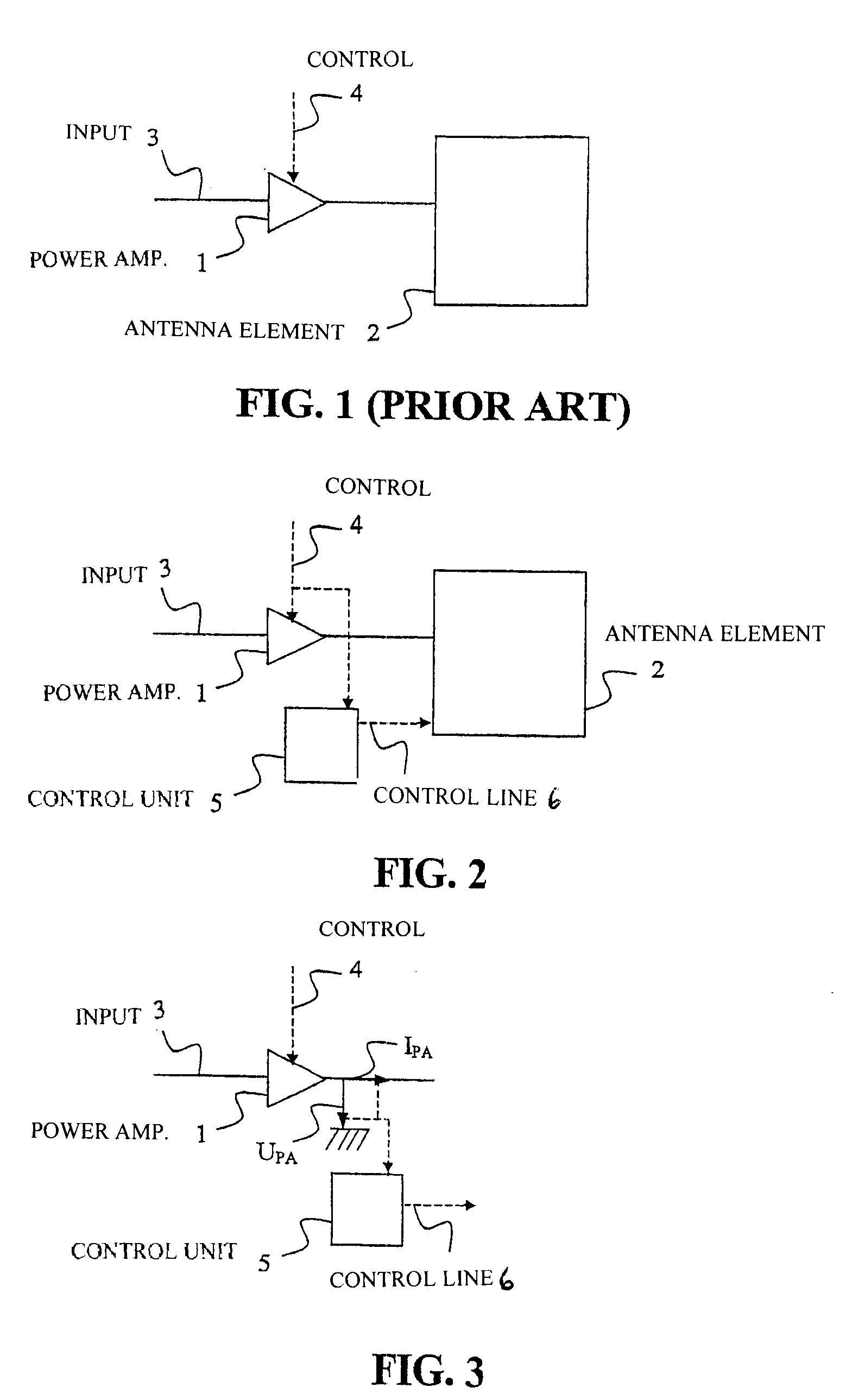
[0029]the present invention will now be described with reference to FIG. 2.

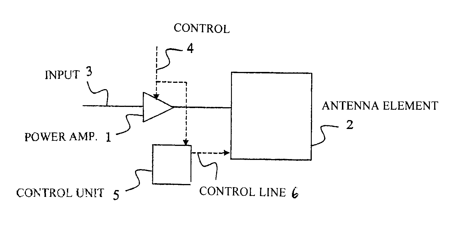
[0030]A portable radio communication device, such as a mobile phone, comprises a power amplifier (PA) 1, an antenna element 2, and a control unit 5. The PA 1 is utilized to amplify a transmission signal fed to an input 3 of the PA 1. The level of the output power from the PA 1 is determined by the input power or a signal 4 indicative of a desired transmission power from the mobile phone. The signal 4 may be a direct power class or an amount of decrease / increase. The desired power of output signal is typically continuously received from a base station indicating the necessary transmission power from the mobile phone.

[0031]The amplified transmission signal is fed to the antenna element 2 for the transmission of the signal to the base station. Between the PA 1 and the antenna element 2 there may be provided filters and switches (not illustrated) e.g. to obtain desired transmission frequencies, to obtain differen...


PUM


Abstract

The present invention relates to a method and an arrangement for optimizing the efficiency of a power amplifier (1) that is utilized for transmission of radio signals in a portable radio communication device, such as a mobile phone. The impedance loading the power amplifier (1) is controlled by a controller (5) in dependence on a transmission power of the portable radio communication device, wherein the radiating impedance of an antenna element (2) loading the power amplifier is controlled in dependence of the desired load impedance. Preferably, the changing of radiating impedance is performed by changing a capacitive coupling between the antenna element and a ground element or by changing the size of the antenna element. Better efficiency and bandwidth are thereby attained.

Description

FIELD OF INVENTION[0001]The present invention generally relates to a power amplifier in a portable radio communication device. Particularly, the present invention relates to a method and an arrangement for optimizing the efficiency of a power amplifier in a portable radio communication device.BACKGROUND[0002]New mobile communication systems are continuously being developed and more and more functions tend to be integrated into the mobile phone terminals, causing increased power consumption in the terminals. It is difficult to improve the capacity of batteries because the size of the batteries is reduced together with the reduction of size of mobile phones. It is thus of great importance to find ways of reducing the power consumption in mobile phone terminals.[0003]One of the more power consuming components in a mobile phone is the power amplifier in the radio transmitter. A reduction of the power consumption of the power amplifier would be a good contribution to the reduction of the...

Claims


Application Information

Patent Timeline
Patent Type & Authority Patents(United States)
IPC IPC(8): H04B1/04H03C1/62H04B17/00H03F1/02H03F1/56
CPCH03F1/02H03F1/56H04B1/0458Y02B60/50H04B2001/045H03F3/24H03B1/04
Inventor THORNELL-PERS, ANDERS
Owner SAMSUNG ELECTRONICS CO LTD
Why Eureka
Try Eureka