Automatic adaptive equalization method and system for high-speed serial transmission link

a serial transmission link and automatic adaptive equalization technology, applied in the field of data communication, can solve the problems of loss of signal integrity, increase in jitter, and distortion of signals, and achieve the effects of facilitating more extensive analog and logic testing of serdes chips, reducing parasitic load, and small area

Inactive Publication Date: 2007-11-13
INT BUSINESS MASCH CORP
View PDF12 Cites 22 Cited by
  • Summary
  • Abstract
  • Description
  • Claims
  • Application Information

AI Technical Summary

Benefits of technology

[0020]An automated adaptive equalization system for a high-speed serial data link is provided according to preferred aspects of the invention. In such system embodiment of the invention, a common data transmitter (TX) is provided with an up channel receiver (UpchRx) and up channel receiver logic (UpchRxLogic) residing at the data transmitter side, and up channel transmitter (UpchTx) and up channel transmitter logic (UpchTxLogic) residing at the data receiver side. The Up channel transmitter logic analyzes the received data eye opening and calculates FFE tap coefficients (up channel data) for better high frequency loss compensation. The Up channel transmitter receives encoded up channel data from the up channel transmitter logic and transmits data upstream through the channel. The Up channel receiver receives up channel data from the channel and delivers the data to the up channel receiver logic. The Up channel receiver logic decodes the received up channel data from the up channel receiver and accordingly updates FFE tap coefficients.
[0021]According to still other preferred aspects of the invention, an automated method is provided to evaluate channel characteristics by analyzing the eye opening of a received data signal on the data receiver side and then adaptively equalizing the channel through adjustment of FFE tap coefficients of the data transmitter to counteract high frequency loss.
[0025]According to still other preferred aspects of the invention, the ability to connect the up channel receiver to the outputs of the data transmitter within a single chip make the up channel receiver available for monitoring operation of the data transmitter. In such way, the up channel receiver can be utilized as a receiver for receiving test signals outputted by the data transmitter during production verification testing of chips (during either pre-packaging testing at the wafer level, testing at the module level during or after packaging, or both), for analog and logic testing of the data transmitter. The output of the up channel receiver is then transferred as a logic level signal to a scan interface of the chip for output to external test apparatus. The up channel receiver is a light receiver, residing at the very output end of the data transmitter, the up channel receiver having small area and adding negligible parasitic load to the critical high-speed serialized data path.
[0027]Thus, according to this aspect of the invention, the up channel receiver of the SerDes data transmitter and the up channel transmitter of the SerDes receiver facilitate more extensive analog and logic testing of SerDes chips, both at the wafer level and at the module level. Among the testing improved thereby are, for example, the LSSD (logic level scan design) test at the wafer level, DC Macro test at the module level, boundary testing per JTAG (Joint Test Action Group) specification, and on-speed testing of SerDes operation through transmission of a pseudo-random bit sequence (PRBS), for example. With such testing, failing chips can be identified earlier in the process, such as at the wafer level prior to packaging, thereby reducing packaging expense as well as total test time required to identify such failing chips. With better testing at the wafer level, improvements in the production yields of the packaged chips are made possible.

Problems solved by technology

In high-speed serial links of data communications networks, losses in signal integrity occur as a data signal is communicated over a non-ideal channel such as a coaxial cable or a backplane between transmitter and receiver cards at respective ends of a link.
As the data signal propagates through a non-ideal channel, it experiences losses due to non-ideal transmission line effects, as well as lumped parasitic elements that exist in the vias, connectors, package, etc. that occur along the channel and which effectively attenuate high frequency components, and thus, distort the signal.
One result of the distortion is an increase in jitter.
Thus, the eye opening of the received signal is highly correlated with bit error rate.
One of the challenges of a data communications system is to provide a system and method of automatically performing adaptive equalization capable of use with transmission channels having different coupling modes and nominal transmission frequencies.
Another challenge is to provide automatic adaptive equalization to counteract losses at higher frequencies, which are not known a priori, for example, when losses are due to the particular installation of the transmitter, receiver, and transmission channel between them.
The frequency characteristic tends to be spread over a broad range of frequencies, causing signal integrity to be degraded.
However, preset equalization may result in the settings for some SerDes units being incorrectly set, leading to problems.
If less than enough equalization is applied, compensation for high frequency loss will not be very effective.
On the other hand, if too much equalization is applied, excessive power is consumed, and excessive cross-talk noise could be generated and presented to links which carry signals from neighboring SerDes units.
None of them is able to fully analyze the transmission channel characteristics and then accordingly calibrate the equalization parameters.
None of them can optimally compensate high frequency loss due to the transmission channel.

Method used


Image

  • Automatic adaptive equalization method and system for high-speed serial transmission link
  • Automatic adaptive equalization method and system for high-speed serial transmission link
  • Automatic adaptive equalization method and system for high-speed serial transmission link

Examples


Embodiment Construction

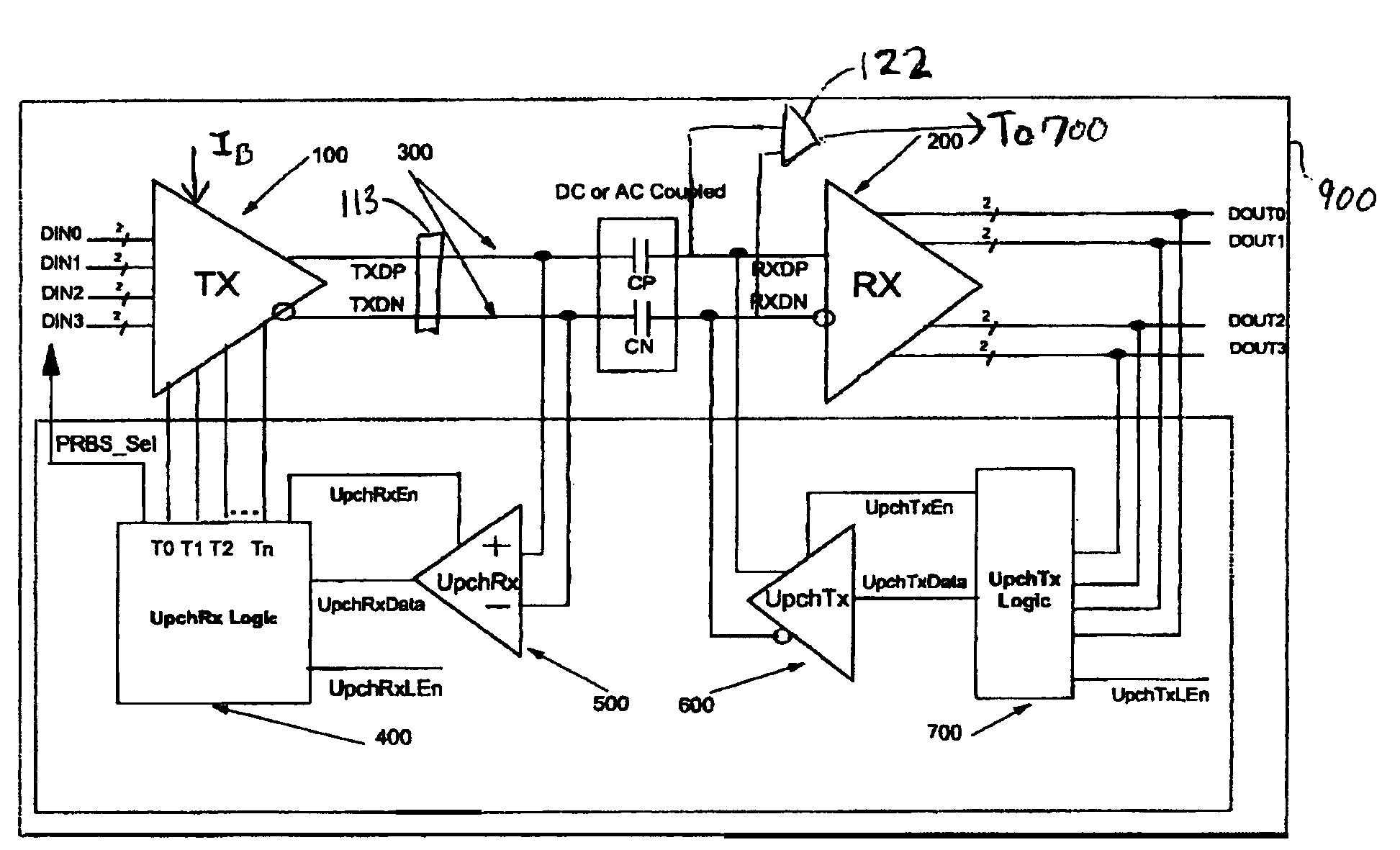
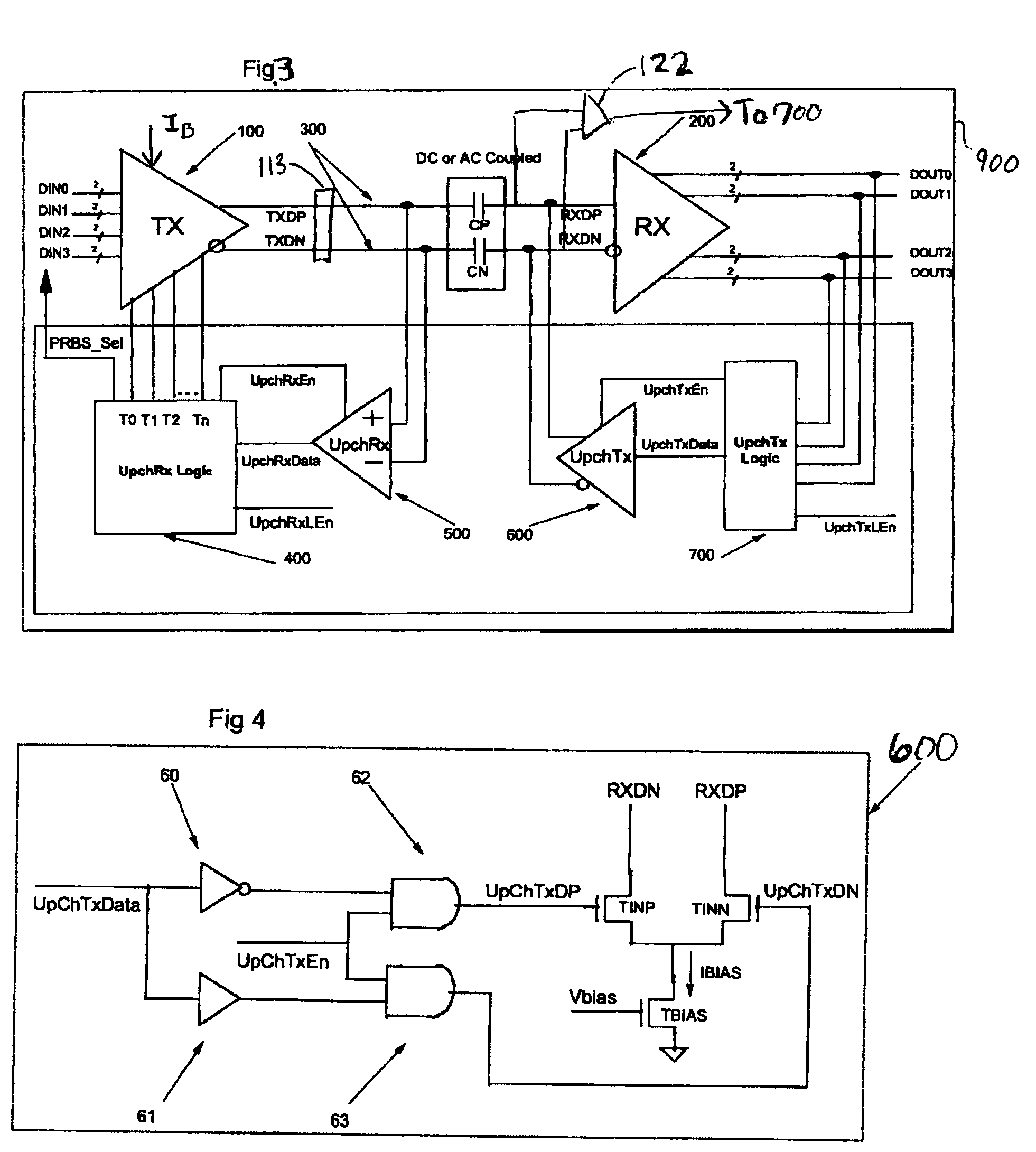
[0037]FIG. 3 is a block diagram illustrating a high-speed serial data transmission system 900 in accordance with an embodiment of the present invention. The system shown on FIG. 3 is called an automated adaptive equalization system. Such system includes a common data transmitter 100 and a common data receiver 200. Parallel input data DIN0, DIN1, DIN2, and DIN3 are supplied to the data transmitter 100, which serializes and outputs the data serially as high-speed differential data signals TXDP and TXDN. These signals are transmitted downstream to the data receiver 200 through a non-ideal transmission channel 300. The differential data signals RXDP and RXDN represent these signals, as modified by passage through the transmission channel 300. The data receiver 200 receives serialized high-speed differential data signals RXDP and RXDN from the transmission channel 300 and de-serializes the received data therefrom back to a parallel format as data signals DOUT0, DOUT1, DOUT2, and DOUT3. T...


PUM


Abstract

A data communication system includes a transmitter unit and a receiver unit. The transmission unit has a transmission characteristic that is adjustable in accordance with equalization information. The transmission unit is operable to transmit a predetermined signal and the receiver unit is operable to receive the predetermined signal. The receiver unit is further operable to generate the equalization information by examining the eye opening of the received signal, and to transmit the equalization information to the transmitter unit.

Description

BACKGROUND OF INVENTION[0001]The present invention relates to data communications.[0002]In high-speed serial links of data communications networks, losses in signal integrity occur as a data signal is communicated over a non-ideal channel such as a coaxial cable or a backplane between transmitter and receiver cards at respective ends of a link. As the data signal propagates through a non-ideal channel, it experiences losses due to non-ideal transmission line effects, as well as lumped parasitic elements that exist in the vias, connectors, package, etc. that occur along the channel and which effectively attenuate high frequency components, and thus, distort the signal. One result of the distortion is an increase in jitter. An effect of jitter is a decrease in the width of the eye opening of the data signal received by a receiver. A narrower eye opening makes individual data bits carried by the data signal less likely to be received correctly, while a wider eye opening makes the bits ...

Claims


Application Information

Patent Timeline
Patent Type & Authority Patents(United States)
IPC IPC(8): H04B3/00H04L25/00H04L25/03
CPCH04L25/03343H04L25/03057
Inventor HSU, LOUIS L.SELANDER, KARL D.SORNA, MICHAEL A.STEPHENS, JEREMY K.XU, HUIHAO
Owner INT BUSINESS MASCH CORP
Why Eureka
Try Eureka