System and method for utilizing an autofocus feature in an automated microscope

an automatic microscope and autofocus technology, applied in the field of automatic microscope autofocus feature utilization system, can solve the problems of inability to perform image acquisition type of image-based autofocus, few existing autofocus systems, etc., and achieve the effect of improving the speed and accuracy of microscope focus adjustmen

Active Publication Date: 2007-11-20
LEICA MICROSYSTEMS CMS GMBH
View PDF9 Cites 18 Cited by
  • Summary
  • Abstract
  • Description
  • Claims
  • Application Information

AI Technical Summary

Benefits of technology

[0012]It is a technical advantage of the present invention that an autofocus method and system for an automated microscope is disclosed. It is another technical advantage of the present invention that a pixel-based optical detector is used to emulate a confocal aperture and / or to improve the speed and accuracy of microscope focus adjustments. It is a further technical advantage of the present invention that the autofocus technique may be useful for confocal or wide-field microscopes.
that an autofocus method and system for an automated microscope is disclosed. It is another technical advantage of the present invention that a pixel-based optical detector is used to emulate a confocal aperture and / or to improve the speed and accuracy of microscope focus adjustments. It is a further technical advantage of the present invention that the autofocus technique may be useful for confocal or wide-field microscopes.

Problems solved by technology

However, very few existing autofocusing systems, if any, can meet such requirements in a cost-efficient way.
Although such a image-based autofocusing system is usually simple, reliable and inexpensive, it is relatively slow since multiple images have to be acquired and then processed with the complex contrast-evaluation algorithm.
In addition, this type of image-based autofocusing cannot be performed during image acquisition (i.e., operate in a “tracking mode”) because the main optical detector would not be available for autofocusing operations.
However, the dedicated autofocusing hardware also substantially increases the overall complexity and cost of the microscope.
Furthermore, a hardware-based autofocusing system is typically incapable of flexible adaptation to different imaging modes the microscope operates in.
However, it is very difficult to implement position-sensitive autofocusing in an imaging system with multiple objective lenses.

Method used


Image

  • System and method for utilizing an autofocus feature in an automated microscope
  • System and method for utilizing an autofocus feature in an automated microscope
  • System and method for utilizing an autofocus feature in an automated microscope

Examples


Embodiment Construction

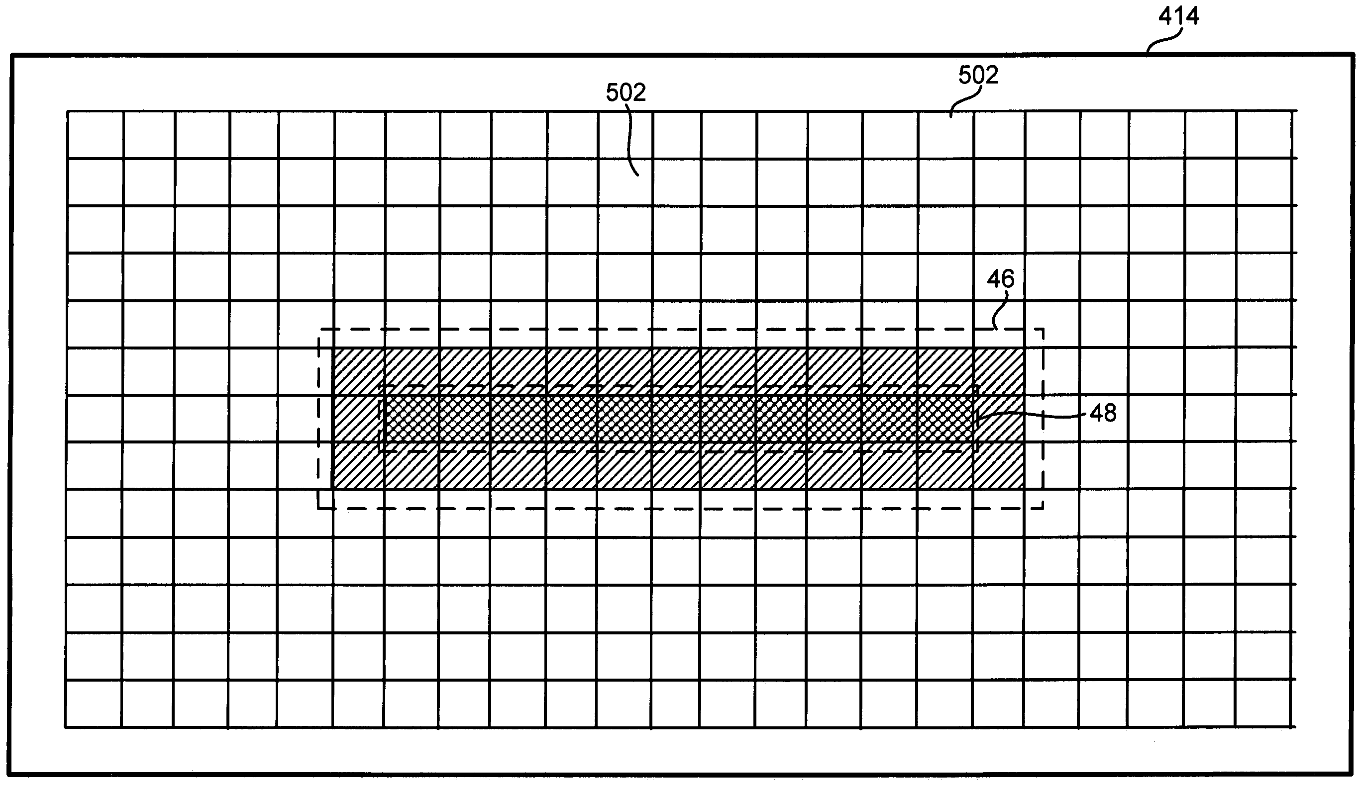
[0021]Embodiments of the present invention introduce a new autofocusing technique that not only provides faster and more accurate focus adjustment than existing image-based autofocusing approaches, but does not require a separate detection system as in existing hardware-based autofocusing systems. These advantages are achieved by using a pixel-based optical detector that serves both as a microscope's main detector for image acquisition and as the detector for autofocus purpose. The pixel-based optical detector may comprise a two-dimensional (2-D) array of sensor pixels whose detection data may be selectively accessed. That is, detection data associated with each sensor pixel in the 2-D array is capable of an independent readout and / or reset. One example of a suitable optical detector may be a complementary metal oxide semiconductor (CMOS) detector having a random access feature. Another example of a suitable optical detector may be a charge-coupled device (CCD) detector. The pixel-b...


PUM


Abstract

The invention relates to a method for adjusting focus in an automated microscope. The method may comprise the steps of: providing an optical detector for image acquisition, wherein the optical detector comprises an array of sensor pixels; designating a region of interest in the array of sensor pixels to emulate a confocal aperture; directing a light beam to illuminate an object according to a predefined pattern, thereby forming an image of the illuminated pattern at the optical detector, wherein the image of the illuminated pattern substantially overlaps the designated region of interest; detecting a light intensity from sensor pixels located within the designated region of interest; and adjusting a relative focal position of an objective lens based on the detected light intensity.

Description

BACKGROUND OF THE INVENTION[0001]Automated microscopes such as confocal laser scanning microscopes and wide-field fluorescence microscopes are powerful imaging tools that are especially valuable for inspection of biological samples. One important component in a typical automated microscope is an autofocusing system. Ideally, the autofocusing system should be able to adjust focus for the microscope's optical system to obtain high-contrast images and should do so in a fast, accurate and reliable manner. However, very few existing autofocusing systems, if any, can meet such requirements in a cost-efficient way. Most known autofocusing systems fall into two categories: image-based or confocal-based, both of which have notable shortcomings.[0002]An image-based autofocusing system may rely on an image-processing algorithm to find a best focus for a microscope. Such an image-based autofocusing system may cause a main optical detector in the microscope to acquire a number of images while an...

Claims


Application Information

Patent Timeline
Patent Type & Authority Patents(United States)
IPC IPC(8): G02B7/04G02B27/40G03B13/00
CPCG02B7/36G02B21/245G02B21/244G02B21/006
Inventor FOMITCHOV, PAVEL A.
Owner LEICA MICROSYSTEMS CMS GMBH
Why Eureka
Try Eureka