Method and device for visualizing computer-generated informations

a computer generated information and information technology, applied in the direction of electrical programme control, program control, instruments, etc., can solve the problems of difficult to make this comprehensible to “robot movices”, experienced users come up against knowledge deficiencies, and serious damage or even injuries to persons, so as to save time and cost, the effect of reducing qualifications

Active Publication Date: 2007-11-20
KUKA LAB GMBH
View PDF18 Cites 137 Cited by
  • Summary
  • Abstract
  • Description
  • Claims
  • Application Information

AI Technical Summary

Benefits of technology

[0026]The invention permits greater flexibility of the automation of operating sequences by means of robots, because reprogramming is facilitated.
[0027]The invention makes the putting into operation, programming and operating of robots more simple and efficient. The invention more particularly relates to groups of robots of complex installations having additional robot components, such as conveying installations.
[0033]The inventive visualization of the selected reference coordinate system or robot axes on the real robot system by means of augmented reality (AR), makes it more easily for the user to foresee the manual displacement, particularly by means of the robot system displacement keys.
[0034]The manipulatability of the reference coordinate systems made possible by the invention makes it unnecessary for the user to learn and carry out cumbersome, complicated measurement methods. A manipulation of augmented, virtual objects is intuitive, saves time and cost and only requires reduced qualifications on the part of the user.
[0037]Apart from the visualizing of virtual elements, such as coordinate systems or robot axes or also real elements in virtual form, such as a control unit on a manual programmer, together with the image of the real robot according to a highly preferred development it is also possible to visualize a robot and its movement sequence in a real environment and with the real workpieces present there. This reduces the risk of damage to things and injury to people. The time exposure is reduced, because the augmented robot can move at random speed, even if people are in its immediate vicinity.
[0041]According to a further development for adapting a robot path to the position of a determined real workpiece, a virtual image of the workpiece is faded in together with a robot path adapted thereto, so that by superimposing the virtual workpiece image and the path points of the robot with the image of the real workpiece it is possible to adapt the robot path to be performed to the position of the real workpiece.

Problems solved by technology

An error can lead to serious damage or even injuries to persons.
However, it is often difficult to make this comprehensible to “robot movices”, because they do not generally have the corresponding mathematical qualifications.
Even experienced users come up against knowledge deficiencies when new configurations occur, such as other “tools” and / or “workpieces”, particularly as measurements are rarely performed.
The measurement procedure can be very complex and involves a considerable amount of time.
A careful procedure is necessary, because an imprecise positioning can lead to a measurement method yielding no or no reliable results.
The lack of visibility of the measurement results also leads to uncertainty as to whether a good measurement result exists or whether it has been falsified by method errors, incorrect inputs, etc.
The path points of programs produced offline by means of a simulation must frequently subsequently be taught in situ, because the geometry of the simulation model and the real robot use environment seldom precisely coincide to an adequate extent.
As robots may only move very slowly when humans are in the vicinity and the target position must be moved up to precisely, teaching or afterteaching is time-consuming.
Moreover, despite the slow movement there is always a certain risk of damage to things and injury to people.
This risk more particularly exists in the case of newly produced robot programs (e.g. offline by means of a simulation), which the programmer must allow to run on the robot for testing purposes.
When a problem or fault occurs in operation, the robot is frequently moved back along the programmed path.
In such or other complex situations, the behavior of the robot system cannot be directly foreseen by the user.
Here again damage to things and injury to people can occur.
The fixing of operating areas in such an installation presupposes complicated measurement.
The monitoring or adaptation of fixed operating areas in the plant is also very complicated, because no optical representation or display exists.
It is unclear in the plant whether and in which zones the attainable operating areas of robot systems overlap, so that a collision risk exists.
Fixing or modifying virtual fixtures or operating areas during programming exceeds the necessary conception capacity of many users, so that it is not immediately apparent to the user in which directions a path and / or rotary movement of the robot or more precisely its tool center point or TCP is possible or is blocked.
As the user cannot foresee the behaviour of the robot system, the user is made uncertain.
As a result of incorrect manipulation, such as e.g. the exerting of high forces in one direction, which are blocked by a virtual fixture, damages can arise on the robot system.
In this situation the subsequent tracking of one specific manual programmer with the associated robot connecting cable during the putting into operation and programming of a robot system and also possibly during subsequent operation takes much effort and time, so that in practice use is generally made of the trial and error method, in which a manual programmer is carefully operated and a check is made as to whether the desired robot moves and if not another manual programmer is tried out.

Method used


Image

  • Method and device for visualizing computer-generated informations
  • Method and device for visualizing computer-generated informations
  • Method and device for visualizing computer-generated informations

Examples


Embodiment Construction

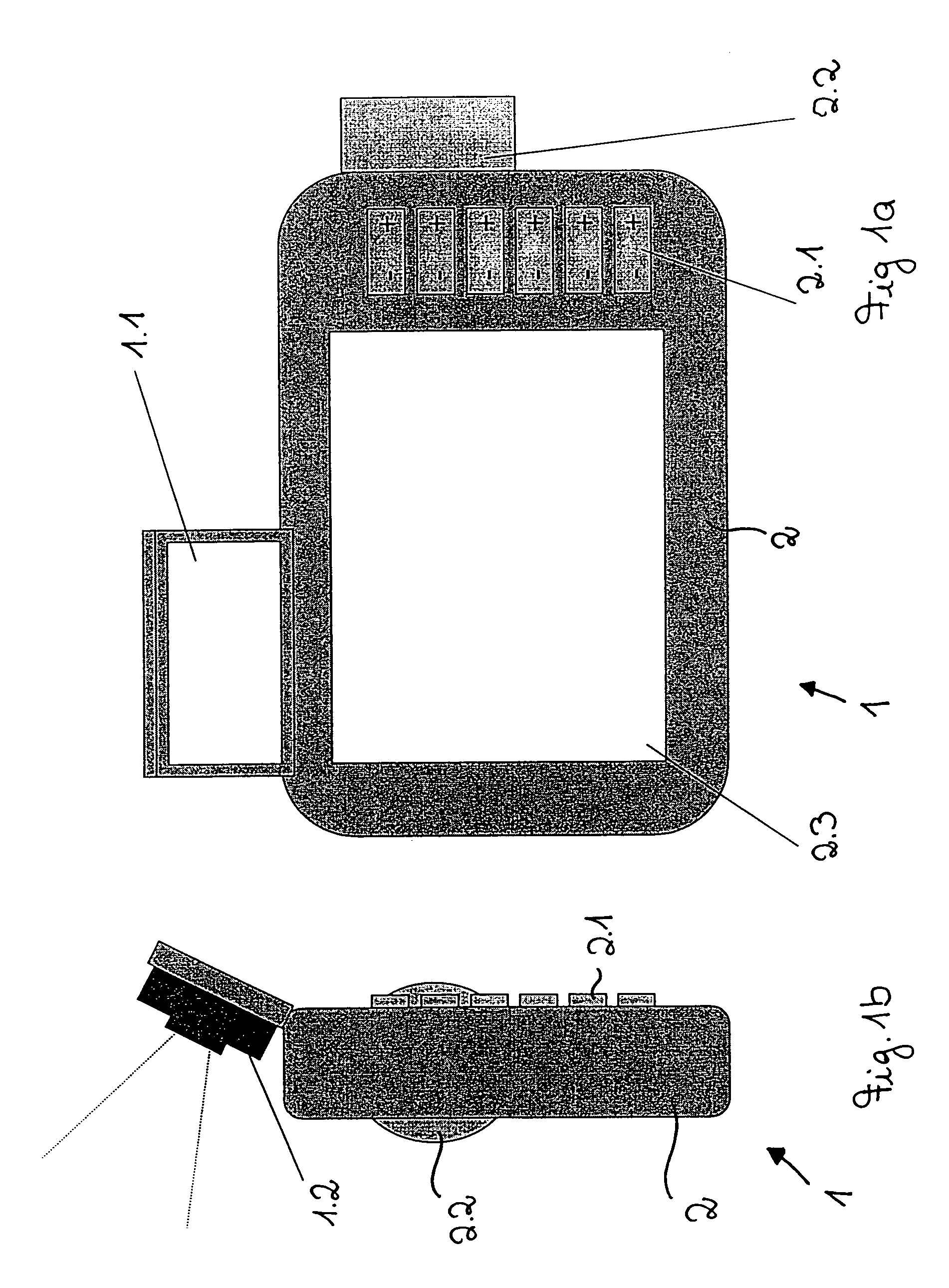
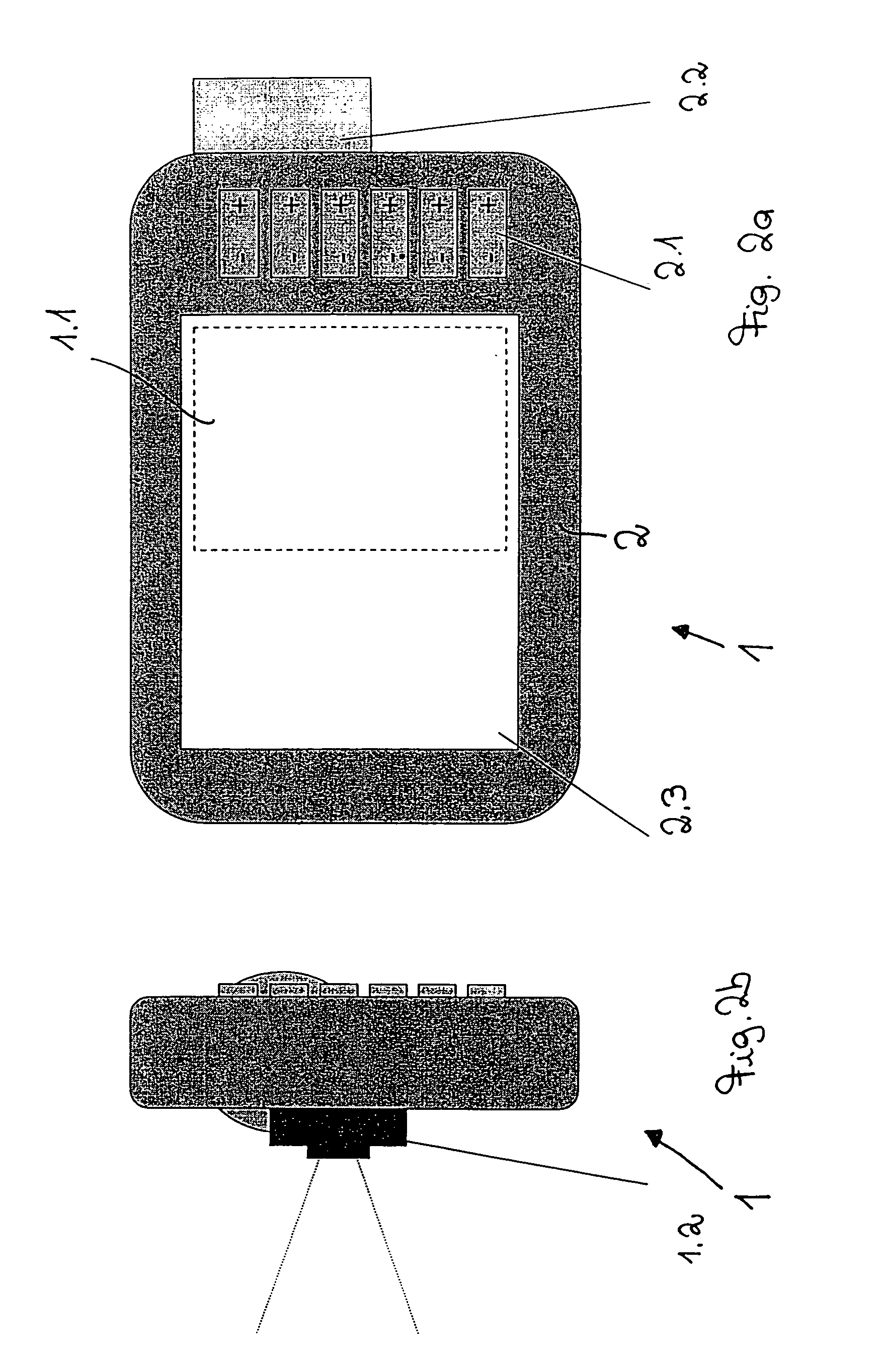
[0063]Referring to the drawings in particular FIGS. 1a and 1b show a first embodiment of an inventive device 1 for fading computer-generated informations into an image of the real environment on a display.

[0064]The device 1 according to the invention has a manual programmer 2 for a robot with which the operating sequence of a robot can be comfortably programmed. The manual programmer 2 is provided for this purpose with control or operating elements in the form of six displacement keys 2.1 and a 6D mouse 2.2 by means of which the movements of the six axes of a robot can be controlled in the same way as through the keys 2.1. Such a manual programmer is known from EP 840 910 (corresponding to U.S. Pat. No. 6,134,102) or EP 840 909 (corresponding to U.S. Pat. No. 6,362,813), to which explicit reference is made in connection with the disclosure of such a manual programmer. The manual programmer 2 also has a screen 2.3 on which are displayed information and data of the control program, su...


PUM


Abstract

To improve the operation of robots in installations reprogramming and emptying an operating sequence to be performed by them, the invention provides a method and a device for visualizing computer-assisted information in an image of the real environment on a viewing device, in which there is a determination of the position and orientation or pose of the image receiving device and that robot-specific informations corresponding to this determination are faded over the image of the real environment on the viewing device.

Description

CROSS REFERENCE TO RELATED APPLICATIONS[0001]This application claims the benefit of priority under 35 U.S.C. §119 of German Patent Application DE 103 05 384.0 filed Feb. 11, 2003, the entire contents of which are incorporated herein by reference.[0002]1. Field of the invention[0003]The present invention to a method and a device for visualizing computer-generated informations.[0004]2. Background of the invention[0005]WO 00 / 52536 discloses displaying computer-generated informations, such as in particular data bank and state informations concerning technical parts together with a real image of the corresponding technical part on a display, especially in text form. The joint display of real images and computer-generated informations is called augmented reality (AR).[0006]In earlier times industrial robots were usually programmed once and for all at the time of putting into operation and then carried out for many years the same task without any change. Within the framework of more flexib...

Claims


Application Information

Patent Timeline
Patent Type & Authority Patents(United States)
IPC IPC(8): G09G5/00G05B19/00G05B19/04G05B19/18G05B19/418G06F19/00B25J9/22B25J9/16G06T1/00G06T7/00G06T15/70G06T17/40
CPCB25J9/1671G06T19/006G06T7/0042G05B2219/35422G05B2219/35506G05B2219/39443G05B2219/39449G05B2219/36167G06T7/73
Inventor KAZI, ARIFKUEPELI, BAHADIRBISCHOFF, RAINER
Owner KUKA LAB GMBH
Why Eureka
Try Eureka