Equalizing optical wavelength routers

a router and optical wavelength technology, applied in the field of optical channel routers, can solve problems such as compromise the integrity of channel information

Inactive Publication Date: 2007-11-20
II VI DELAWARE INC
View PDF17 Cites 13 Cited by
  • Summary
  • Abstract
  • Description
  • Claims
  • Application Information

AI Technical Summary

Benefits of technology

[0012]Exemplary embodiments of the present invention may use one

Problems solved by technology

These unequal intensities can compromise the inte

Method used


Image

  • Equalizing optical wavelength routers
  • Equalizing optical wavelength routers
  • Equalizing optical wavelength routers

Examples


Embodiment Construction

[0019]The present invention provides dynamic equalizing wavelength router. The following description is presented to enable one of ordinary skill in the art to make and use the invention and is provided in the context of a patent application and its requirements. Various modifications to the preferred embodiment will be readily apparent to those skilled in the art and the generic principles herein may be applied to other embodiments. Thus, the present invention is not intended to be limited to the embodiment shown but is to be accorded the widest scope consistent with the principles and features described herein.

[0020]To more particularly describe the features of the present invention, please refer to FIGS. 1 through 5 in conjunction with the discussion below.

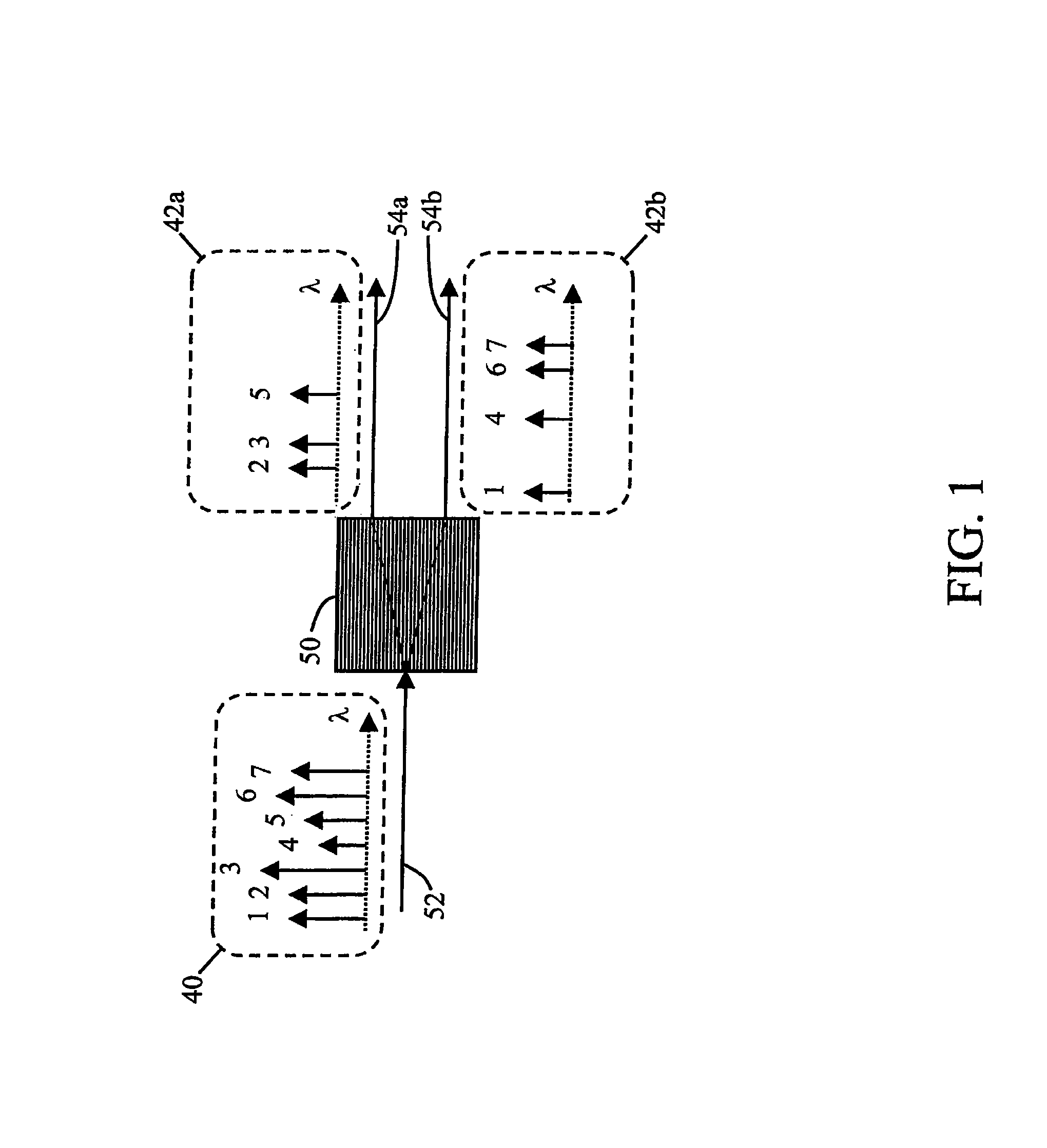
[0021]A functional diagram of dynamic equalizing wavelength routers is illustrated in FIG. 1. A hypothetical spectrum of the incoming aggregated optical signal is shown in box 40. This incoming signal is input to the dynamic eq...


PUM


Abstract

A dynamic equalizing optical channel router includes an input port for receiving a wavelength division multiplexed composite optical signal comprising a plurality of channels; at least one output port; a diffraction grating optically coupled to the input and output ports; a lens optically coupled to the diffraction grating at a side opposite to the input and output ports; an array of steering devices optically coupled to the lens at a side opposite to the diffraction grating, wherein each channel is reflected by a different steering device of the array; and a plurality of attenuators, wherein each channel reflected by the array traverses one of the attenuators and the diffraction grating to the at least one output port. The router is able to dynamically adjust optical intensity of each wavelength channel by a different amount while also performing the function of wavelength routing.

Description

CROSS-REFERENCE TO RELATED APPLICATIONS[0001]This application claims priority under 35 U.S.C §119(e) the benefit of U.S. Provisional Patent Application Ser. No. 60 / 314,351, entitled “Dynamic Equalizing Optical Wavelength Routers,” filed on Aug. 22, 2001.FIELD OF THE INVENTION[0002]The present invention relates to optical channel routers that can independently route each of a plurality of wavelength division multiplexed optical channels to one of two separate outputs. More particularly, the present invention relates to such optical channel routers wherein, additionally, the relative intensities of the channels are equalized.BACKGROUND OF THE INVENTION[0003]In a wavelength division multiplexing optical communication system, information is carried by multiple channels each with a distinct wavelength. It is often necessary to add or drop a wavelength channel in optical links or networks. This can be achieved by a wavelength router that sends different wavelength channels to different lo...

Claims


Application Information

Patent Timeline
IPC IPC(8): G02F1/01G02B5/18G02B5/30H04J14/02H04J14/06G02B6/34
CPCG02B6/2931G02B6/2938G02B6/29314
Inventor PENG, SONGLI, MING
Owner II VI DELAWARE INC
Why Eureka
Try Eureka