Magnetic recording medium and magnetic recording device using the same

a recording medium and magnetic recording technology, applied in mechanical recording, light beam reproducing, instruments, etc., can solve the problem of not being able to obtain sufficient pinning effect, achieve the effect of suppressing magnetic wall movement, reducing recording track width, and improving signal quality

Inactive Publication Date: 2007-11-20
SHARP KK
View PDF33 Cites 0 Cited by
  • Summary
  • Abstract
  • Description
  • Claims
  • Application Information

AI Technical Summary

Benefits of technology

[0018]According to the arrangement, the magnetic layer has the bumps whose density is not less than 400 bumps / μm2 on its surface, so that the number of the minute bumps is so sufficient that the bumps function as a pinning site for suppressing the magnetic wall movement of the magnetic layer, thereby making the movement distance short. Thus, even though the magnetic layer is made of amorphous magnetic material which tends to cause the magnetic wall movement, it is possible to stably form a minute recording bit whose recording bit length is short on the magnetic recording medium. Further, it can be said that the pinning effect is particularly useful in a magnetic recording medium having a magnetic layer made of amorphous magnetic material. Thus, also in a case of performing high-density recording, it is possible to obtain sufficient signal quality.
[0034]Further, in the thermal assist magnetic recording system, a recording region (recording bit) is heated in recording information, so that a coercive force of the magnetic layer drops and magnetic anisotropy of the magnetic layer largely drops. Thus, in the thermal assist recording system, the magnetic wall movement tends to occur, so that it is more important to suppress the magnetic wall movement caused by the bumps formed on the surface of the magnetic layer. As a result, in the thermal assist magnetic recording system, it is possible to further improve the signal quality in causing the bumps formed on the surface of the magnetic recording medium to perform the high-density recording.

Problems solved by technology

While, when the density of the bumps is less than 400 bumps / μm2, the number of the bumps functioning as the pinning site is so small that it is impossible to obtain the sufficient pinning effect.

Method used


Image

  • Magnetic recording medium and magnetic recording device using the same
  • Magnetic recording medium and magnetic recording device using the same
  • Magnetic recording medium and magnetic recording device using the same

Examples


example 1

[0087]The following description will explain a process of manufacturing a magnetic recording medium as an example.

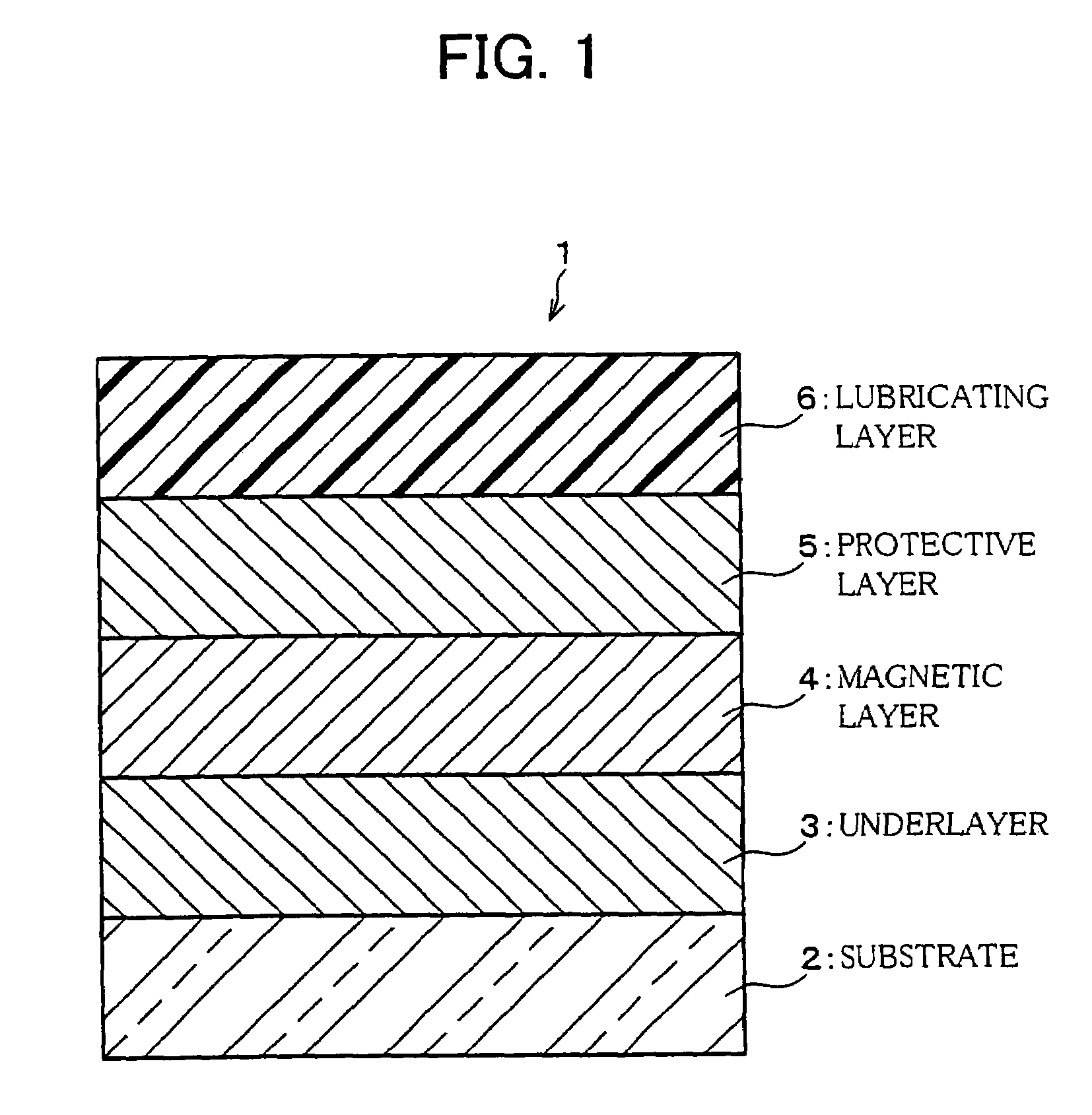
[0088]First, an aluminium film (hereinafter, referred to as “Al underlayer”) which functioned as the underlayer 3 was formed on a glass disk substrate which functioned as the substrate 2 so that its average film thickness was 3.7 nm. The aluminium film was formed in accordance with a direct current magnetron sputtering process at a sputtering pressure of 0.5 Pa.

[0089]Next, a TbFeCo film was formed on a surface of the Al underlayer as the amorphous magnetic layer 4 so that its film thickness was 50 nm. The TbFeCo film was formed in accordance with a direct current magnetron sputtering process at a sputtering pressure of 0.45 Pa. Note that, the TbFeCo film was formed by using an alloy made of Tb23 atomic % (hereinafter, referred to “at %”), Fe60 at %, and Co17 at % as a target in sputtering. Thus formed TbFeCo film was such that: its magnetic compensation point (compensati...

example 2

[0094]Next, surfaces of magnetic layers of the magnetic recording media of Example 1, Comparative Example 1, and Comparative Example 2 were observed from normal direction thereof by means of an atom force microscope (AFM). Micrograms of Example 1, Comparative Example 1, and Comparative Example 2 are respectively shown in FIG. 3, FIG. 4, and FIG. 5.

[0095]In order to observe the surface of the magnetic layer of each of the magnetic recording media of Example 1, Comparative Example 1, and Comparative Example 2, the protective layer 5 and the lubricating layer 6 were omitted from each magnetic recording medium so that its outermost surface was the amorphous magnetic layer 4, thereby obtaining samples. That is, the sample of Example 1 was obtained by providing the aluminium film (underlayer 3) and the TbFeCo film (amorphous magnetic layer 4) on and above the glass disk substrate (substrate 2), and the sample of Comparative Example 1 was obtained by providing the TbFeCo film on the glass ...

example 3

[0099]Next, surface shapes of the magnetic recording media manufactured in Example 1 and Comparative Example 1 were observed by means of an atom force microscope (AFM).

[0100]The surfaces of the magnetic recording media of Example 1 and Comparative Example 1, that is, the surfaces of the lubricating layers 6 were observed from its normal direction by means of the atom force microscope, and the observed surfaces are respectively shown in FIG. 6 and FIG. 7.

[0101]As shown in FIG. 6, in the surface of the magnetic recording medium of Example 1 in which the Al film was provided as the underlayer 3, minute bumps (diameter of each bump was approximately 30 nm) formed on the surface in a high-density manner were observed. Further, at this time, the height of bumps (length from a bottom to a top of the bump) was approximately 4 nm. Here, the layer thickness of the magnetic layer 4 was 50 nm, so that the height of bumps corresponds to 8% with respect to the layer thickness of the magnetic laye...


PUM

PropertyMeasurementUnit
diameteraaaaaaaaaa
thicknessaaaaaaaaaa
melting pointaaaaaaaaaa

Abstract

A magnetic recording medium includes: an underlayer constituted of at least a substrate and a nonmagnetic metal element; and an amorphous magnetic layer, made of amorphous magnetic material, which magnetically records information. In certain example embodiments, the amorphous magnetic layer has bumps on a surface thereof or the magnetic recording medium has bumps on a surface thereof (surface of a lubricating layer) so that density of the bumps is not less than 400 bumps / μm2 or so that height of the bumps is not less than 2% with respect to an average layer thickness of the amorphous magnetic layer. Thus, magnetic wall movement of the amorphous magnetic layer is effectively suppressed, so that it is possible to stably form a recording bit.

Description

FIELD OF THE INVENTION[0001]The present invention relates to (i) a magnetic recording medium preferably used in a magnetic recording device which magnetically records information by heating a recording region of a magnetic layer with a light beam (heat source) and by applying a magnetic field to the recording region, and to (ii) the magnetic recording device using the magnetic recording medium.BACKGROUND OF THE INVENTION[0002]Recently, (i) an optical memory represented by Blu-ray Disk (BD) or an optical magnetic disk and (ii) a magnetic memory represented by a hard disk have been drastically modified in a high-density manner. As one of high-density magnetic recording / reproduction techniques, a thermal assist magnetic recording / reproduction system has been being developed. For example, U.S. Pat. No. 5,656,385 registered on Aug. 12, 1997 (corresponding to Japanese Unexamined Patent Publication No. 176034 / 1992 (Tokukaihei 4-176034): hereinafter, referred to as Patent Document 1) disclo...

Claims


Application Information

Patent Timeline
Patent Type & Authority Patents(United States)
IPC IPC(8): G11B5/02G11B5/82G11B5/65G11B5/00G11B5/127G11B5/64G11B5/73G11B5/738G11B5/74G11B11/10G11B11/105
CPCG11B5/127G11B5/64G11B5/7325G11B5/74G11B5/82G11B2005/0021G11B2005/0002G11B2005/0005G11B2005/001G11B2005/0016G11B11/10591G11B5/7368G11B5/7377
Inventor SATO, JUNICHIFUJI, HIROSHI
Owner SHARP KK
Why Eureka
Try Eureka