Device for optically regenerating pulses, an installation including such a device, and the use of the device

a technology optical fibers, applied in the field of optical regenerating pulses, can solve the problems of destabilizing and disturbing changing the optimum waveform of pulses, and affecting the propagation of such pulses in optical fibers, so as to achieve easy and accurate adjustment, eliminate transmitted pulse noise, and stabilize intensity

a technology optical fibers, applied in the field of optical regenerating pulses, can solve the problems of destabilizing and disturbing changing the optimum waveform of pulses, and affecting the propagation of such pulses in optical fibers, so as to achieve easy and accurate adjustment, eliminate transmitted pulse noise, and stabilize intensity

US7298948B2Inactive Publication Date: 2007-11-20FRANCE TELECOM SA

Image

  • Device for optically regenerating pulses, an installation including such a device, and the use of the device
  • Device for optically regenerating pulses, an installation including such a device, and the use of the device
  • Device for optically regenerating pulses, an installation including such a device, and the use of the device

Examples


Embodiment Construction

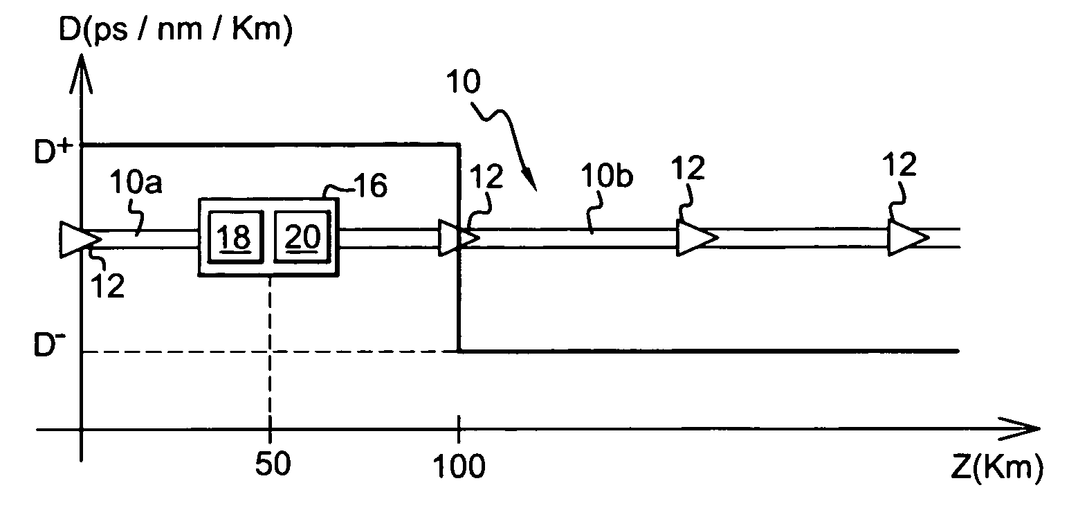
[0034]The optical transmission installation shown in FIG. 1 comprises a line fiber 10 forming means for propagating a light signal.

[0035]The light signal in question is made up of a plurality of frequency-multiplexed channels. The multiplexed frequencies are multiples of a frequency f0.

[0036]Each channel is made up of pulses of the DM soliton type. These pulses are used for very high rate optical transmission applications, e.g. for transmitting at 40 gigabits per second (Gbit / s) or higher. The term “bit time” is used to designate the transmission period of the pulses. The half-height time width of DM soliton pulses is generally of the same order as half the bit time.

[0037]The line fiber 10 has a first portion 10a performing the function of propagation means having abnormal dispersion, with a dispersion coefficient D+ that is equal to 2.55 picoseconds per nanometer per kilometer (ps / nm / km), for example. This first portion of fiber 10a having abnormal dispersion is extended by a secon...


PUM


Abstract

The invention relates to in particular to a device for optically regenerating pulses, the device comprising an optical bandpass filter adapted for providing time synchronization and intensity stabilization of dispersion-managed soliton pulses. The device further comprises noise suppression means distinct from the bandpass filter.

Description

[0001]The present invention relates to a device for optically regenerating pulses, to an installation including such a device, and to the use of the device.[0002]More precisely, the invention relates to regenerating dispersion-managed soliton pulses transmitted over an optical fiber. Dispersion-managed soliton pulses are also referred to as DM soliton pulses.BACKGROUND OF THE INVENTION[0003]DM soliton pulses have the property of propagating periodically without deformation in a non-linear medium, since these particular pulses constitute a solution to the non-linear Schrödinger equation. Nevertheless, accumulated amplified spontaneous emission noise, in particular as generated by optical amplifiers disposed at regular intervals along the optical fiber, disturbs the propagation of such pulses by generating intensity fluctuations and so-called Gordon-Haus time jitter. Collisions between DM soliton pulses belonging to different channels of the optical fiber also constitute a source of j...

Claims


Application Information

Patent Timeline
20 Nov 2007
Publication
US7298948B2
IPC
G02B6/00; H04B10/2507
CPC
H04B10/25077
Inventors
PINCEMIN, ERWAN