Method and structure to process thick and thin fins and variable fin to fin spacing

a technology of fins and fins, applied in the direction of semiconductor devices, electrical apparatus, transistors, etc., can solve the problem of limiting such structures to devices, and achieve the effect of less fins to fins

Active Publication Date: 2007-11-27
GLOBALFOUNDRIES US INC
View PDF27 Cites 62 Cited by
  • Summary
  • Abstract
  • Description
  • Claims
  • Application Information

AI Technical Summary

Problems solved by technology

Current technology allows an integrated circuit structure to be designed and formed with multiple non-planar devices (e.g., finFETs or trigate FETs) on the same silicon-on-insulator (SOI) wafer but generally limits such structures to devices having the same fin width and to devices having approximately uniform spacing between the fins.

Method used


Image

  • Method and structure to process thick and thin fins and variable fin to fin spacing
  • Method and structure to process thick and thin fins and variable fin to fin spacing
  • Method and structure to process thick and thin fins and variable fin to fin spacing

Examples


Embodiment Construction

Embodiments of the Invention

[0036]The embodiments of the invention and the various features and advantageous details thereof are explained more fully with reference to the non-limiting embodiments that are illustrated in the accompanying drawings and detailed in the following description. It should be noted that the features illustrated in the drawings are not necessarily drawn to scale. Descriptions of well-known components and processing techniques are omitted so as to not unnecessarily obscure the embodiments of the invention. The examples used herein are intended merely to facilitate an understanding of ways in which the embodiments of the invention may be practiced and to further enable those of skill in the art to practice the embodiments of the invention. Accordingly, the examples should not be construed as limiting the scope of the invention.

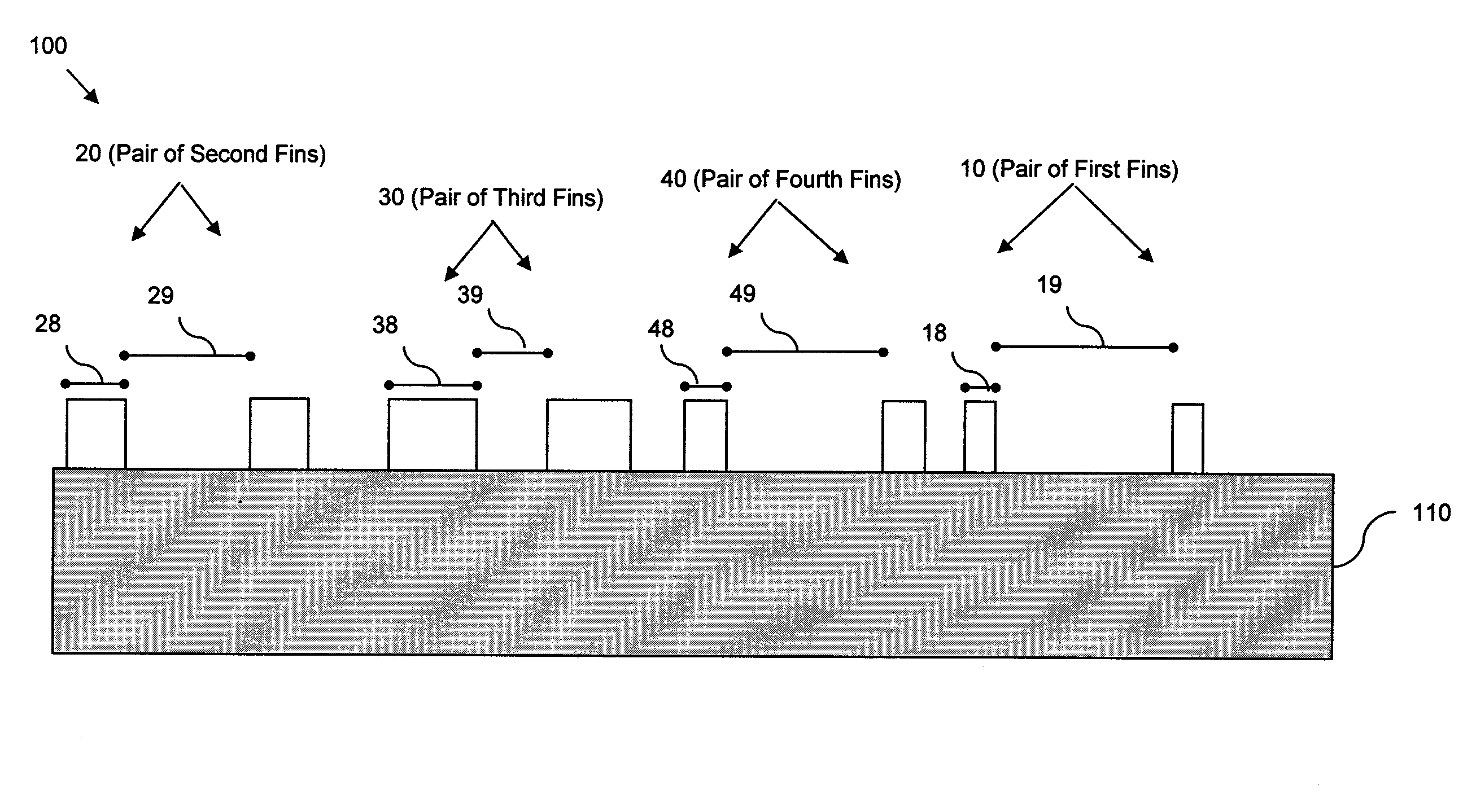
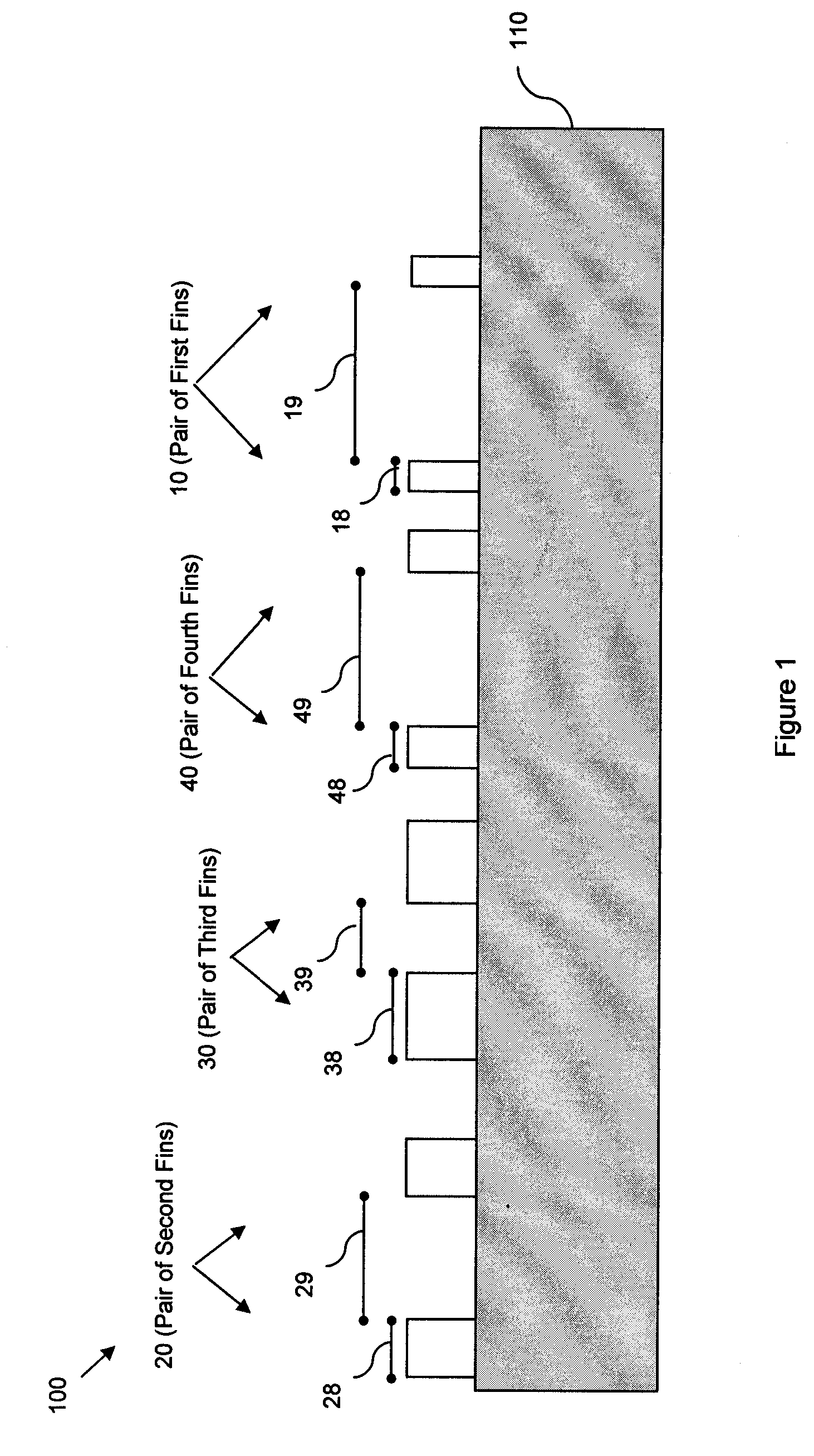
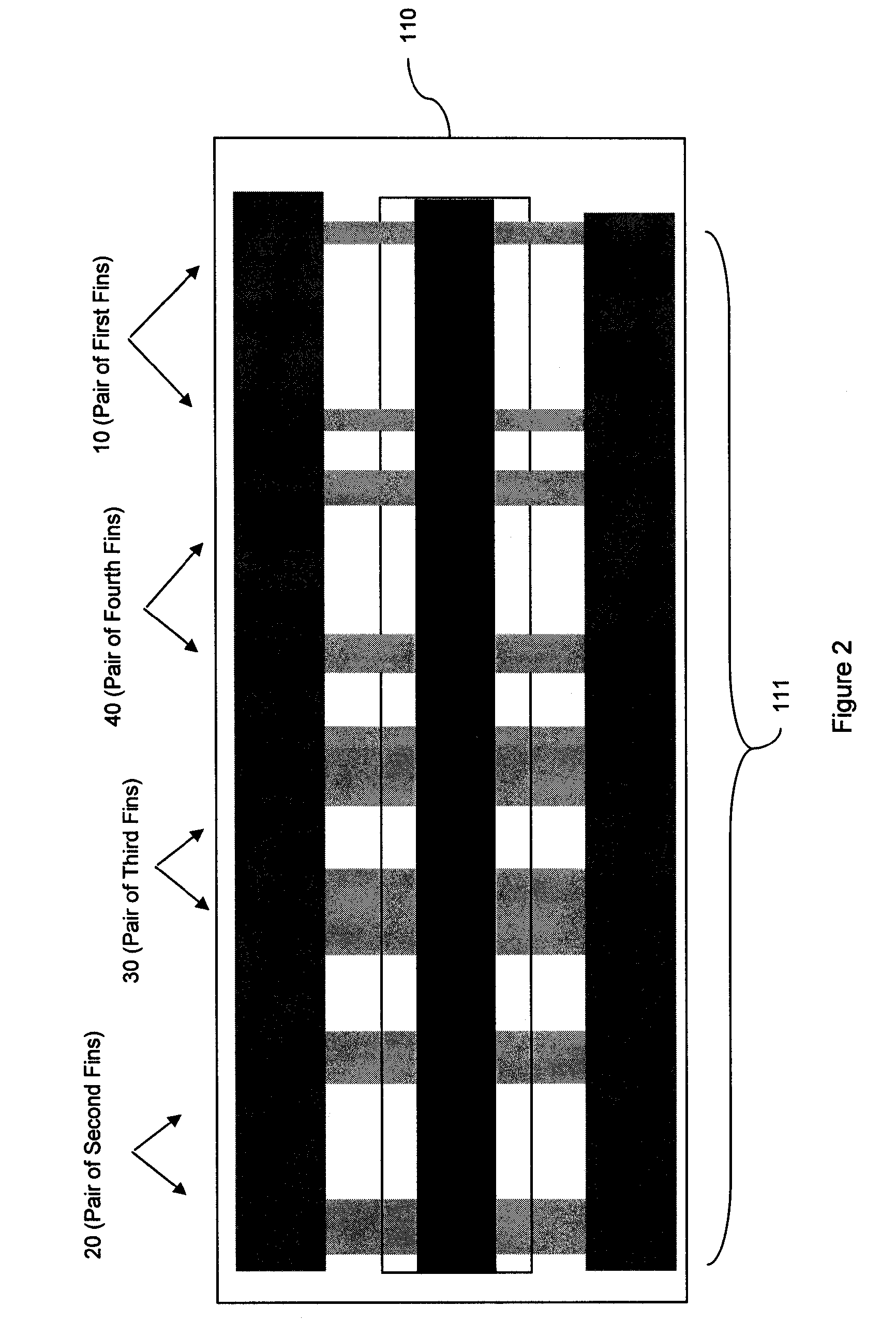
[0037]As mentioned above, current technology allows an integrated circuit structure to be designed and formed with multiple non-planar ...


PUM


Abstract

Disclosed is an integrated circuit with multiple semiconductor fins having different widths and variable spacing on the same substrate. The method of forming the circuit incorporates a sidewall image transfer process using different types of mandrels. Fin thickness and fin-to-fin spacing are controlled by an oxidation process used to form oxide sidewalls on the mandrels, and more particularly, by the processing time and the use of intrinsic, oxidation-enhancing and / or oxidation-inhibiting mandrels. Fin thickness is also controlled by using sidewalls spacers combined with or instead of the oxide sidewalls. Specifically, images of the oxide sidewalls alone, images of sidewall spacers alone, and / or combined images of sidewall spacers and oxide sidewalls are transferred into a semiconductor layer to form the fins. The fins with different thicknesses and variable spacing can be used to form a single multiple-fin FET or, alternatively, various single-fin and / or multiple-fin FETs.

Description

BACKGROUND OF THE INVENTION[0001]1. Field of the Invention[0002]The invention generally relates to integrated circuit structures, and more particularly, to an integrated circuit structure comprising multiple non-planar semiconductor bodies with different thicknesses and with variable spacing between the semiconductor bodies.[0003]2. Description of the Related Art[0004]Integrated circuit design decisions are often driven by device scalability and manufacturing efficiency. For example, multi-gated non-planar field effect transistors (FETs), such as double gate or tri-gate FETs, were developed to provide scaled devices with larger drive currents and reduced short channel effects over planar FETs. Double gate FETs (e.g., fin-type FETs (finFETs) are non-planar transistors in which a channel is formed in a center region of a thin semiconductor fin with source and drain regions at opposing ends. Gates are formed on the opposing sides of the thin semiconductor body adjacent the channel. The...

Claims


Application Information

Patent Timeline
Patent Type & Authority Patents(United States)
IPC IPC(8): H01L29/76H01L29/94H01L31/062H01L31/113H01L31/119
CPCH01L21/845H01L29/785H01L27/1211
Inventor ABADEER, WAGDI W.BROWN, JEFFREY S.CHATTY, KIRAN V.GAUTHIER, JR., ROBERT J.RANKIN, JED H.TONTI, WILLIAM R.
Owner GLOBALFOUNDRIES US INC
Why Eureka
Try Eureka