Supercharge Your Innovation With Domain-Expert AI Agents!

Electric car control apparatus

a technology for controlling apparatus and electric cars, applied in the direction of electric generator control, dynamo-electric converter control, dynamo-electric gear control, etc., can solve the problems of low accuracy of half voltage calculated from the voltage detected from these two voltage sensors, abnormal voltage applied, and device size excessive, so as to achieve high accuracy control and improve accuracy. the effect of voltage detection

Inactive Publication Date: 2007-11-27
MITSUBISHI ELECTRIC CORP
View PDF12 Cites 2 Cited by
  • Summary
  • Abstract
  • Description
  • Claims
  • Application Information

AI Technical Summary

Benefits of technology

This configuration enhances voltage detection accuracy and reduces apparatus size by eliminating the need for a current sensor, allowing for precise control of the three level inverter.

Problems solved by technology

However, when a voltage across opposite ends of each filter capacitor becomes higher than an ordinary voltage owing to a rapid variation of a load or the like, an abnormal voltage will be applied to a semiconductor device of the three level converter.
In this method, however, when the AC switch does not perform normal opening operation due to a failure or the like, a current detector for detecting a current flowing through the overvoltage suppression resistor is required so as not to invite a heated burnout of the overvoltage suppression resistor, thus resulting in that the device becomes excessively large.
However, in case where the resolution of the first voltage sensor is lower than the resolution of the second voltage sensor, the upstream half voltage calculated from the voltage detected from these two voltage sensors is lower in accuracy than the downstream half voltage directly detected, and as a result, the accuracy of the control also becomes low.

Method used


Image

  • Electric car control apparatus
  • Electric car control apparatus
  • Electric car control apparatus

Examples


embodiment 1

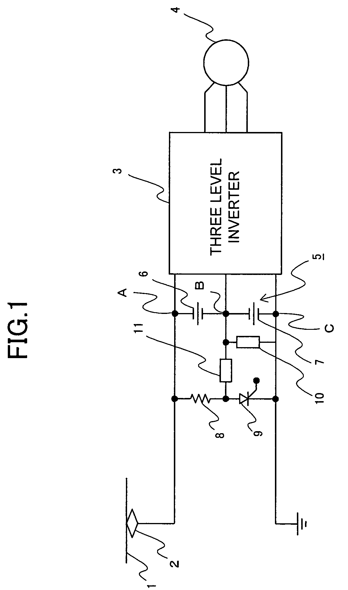
[0015]FIG. 1 is a block diagram that shows an electric car control apparatus according to a first embodiment of the present invention. In FIG. 1, DC power collected from overhead wiring 1 by means of a pantograph 2 is input to a three level inverter 3 having a maximum potential terminal A, an intermediate potential terminal B and a minimum potential terminal C, where it is converted to AC power to drive an induction motor 4. In addition, a filter capacitor circuit 5, which serves to divide a DC voltage between terminals of the three level inverter 3 into two voltage components, is connected in parallel to the three level inverter 3. The filter capacitor circuit 5 is composed of an upstream filter capacitor 6 (upstream side capacitor) and a downstream filter capacitor 7 (downstream side capacitor) connected in series with each other. The upstream filter capacitor 6 is connected between the maximum potential terminal A and the intermediate potential terminal B of the three level inver...

embodiment 2

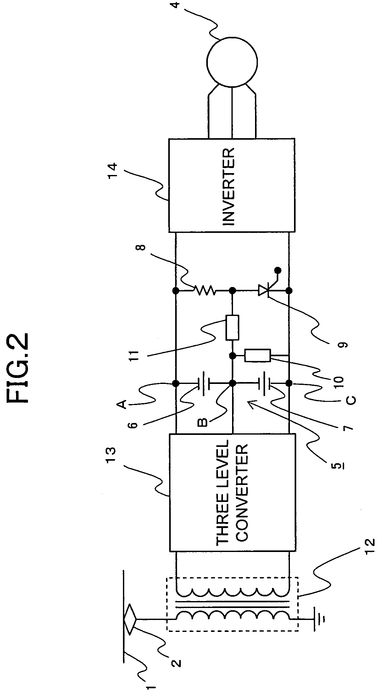
[0024]FIG. 2 is a block diagram that shows an electric car control apparatus according to a second embodiment of the present invention. In FIG. 2, AC power supplied by the overhead wiring 1 is input to the three level converter 13 through transformer 12, and DC power output from the maximum potential terminal, the intermediate potential terminal and the minimum potential terminal is input to an inverter 14. The construction of the second embodiment other than the above is similar to that of the first embodiment.

[0025]In the three level converter 13, the two voltage sensors connected in series are connected in parallel to the thyristor 9 so as to detect a DC full voltage, and for detection of a half voltage, the junction of the two voltage sensors connected in parallel to the thyristor 9 is connected to the junction of the upstream filter capacitor 6 and the downstream filter capacitor 7. Consequently, it is possible to make the resolutions of the voltage sensors equal to each other,...


PUM


Abstract

In an electric car control apparatus for driving an induction motor, detection accuracy of a DC voltage is improved. A DC power supply device is provided which has a maximum potential terminal A, an intermediate potential terminal B, a minimum potential terminal C, an upstream side capacitor 6 between the maximum potential terminal A and the intermediate potential terminal B, and a downstream side capacitor 7 between the intermediate potential terminal B and the minimum potential terminal C. Also, an overvoltage suppression part is provided which includes a resistor 8 and a thyristor 9 between the maximum potential terminal A and the minimum potential terminal C. Further, provision is made for a downstream voltage sensor 10 between the intermediate potential terminal B and the minimum potential terminal C, an upstream voltage sensor 11 between a junction of the resistor 8 and the thyristor 9 and the intermediate potential terminal B, and a three level inverter 3 connected to the maximum potential terminal A, the intermediate potential terminal B and the minimum potential terminal C for supplying AC power to the induction motor. The three level inverter 3 is controlled by using detected voltages of the downstream voltage sensor 10 and the upstream voltage sensor 11.

Description

[0001]This application is based on and claims priority to Japanese Application No. 2004-232483, filed Aug. 9, 2004 and International Application No. PCT / JP2005 / 006503, filed Apr. 1, 2005 designating the U.S., the entire contents of both of which are hereby incorporated by reference.TECHNICAL FIELD[0002]The present invention relates to an electric car control apparatus for controlling and driving an induction motor of an electric car.BACKGROUND ART[0003]A known power conversion device with a three level (PWM) converter has two DC voltage detectors that are provided for two filter capacitors, respectively, connected with a DC side of the three level converter for detecting the individual voltages of the capacitors, and the three level converter is PWM controlled based on the voltages of the filter capacitors detected by the two DC voltage detectors, respectively (see, for example, a first patent document).[0004]However, when a voltage across opposite ends of each filter capacitor beco...

Claims


Application Information

Patent Timeline
Patent Type & Authority Patents(United States)
IPC IPC(8): H02M5/453H02P27/06B60L9/18H02M7/12H02M7/483
CPCB60L9/22H02M7/483B60L11/00B60L2220/12B60L50/00H02M7/217B60L9/18H02M7/48H02M7/12
Inventor NAGATSUKA, YOSHIOMATSUMOTO, TAKEOKAWAMOTO, SHOUICHI
Owner MITSUBISHI ELECTRIC CORP
Features
  • R&D
  • Intellectual Property
  • Life Sciences
  • Materials
  • Tech Scout
  • Unparalleled Data Quality
  • Higher Quality Content
  • 60% Fewer Hallucinations
Learn More