Interleaving.deinterleaving device and method for communication system

a communication system and interleaving technology, applied in the field of communication systems, can solve the problems of memory loss, reduced memory efficiency of interleavers, and inability to express them in terms of power of 2;

Inactive Publication Date: 2007-11-27
SAMSUNG ELECTRONICS CO LTD
View PDF15 Cites 13 Cited by
  • Summary
  • Abstract
  • Description
  • Claims
  • Application Information

AI Technical Summary

Benefits of technology

[0055]As described above, the invention has proposed an effective address generating method for various interleaver sizes which cannot be expressed in terms of a power of 2. This solves the low memory efficiency problem of the existing interleaver. In addition, it is possible to generate an address for various interleaver sizes using a single algorithm. Therefore, it is not necessary for the host (or CPU) to store separate interleaving rules for the respective interleaver sizes, thereby saving memory capacity. Furthermore, the interleaver memory uses only the capacity corresponding to the frame size N, thus increasing memory efficiency.
[0056]While the invention has been shown and described with reference to a certain preferred embodiment thereof, it will be understood by those skilled in the art that various changes in form and details may be made therein without departing from the spirit and scope of the invention as defined by the appended claims.

Problems solved by technology

However, an interleaver having a size which cannot be expressed in terms of a power of 2 has a reduced memory efficiency.
Therefore, 28672 (=65536−36864) bits are unused in the memory, thereby causing a memory loss.
In addition, even though the memory has a sufficient capacity, it is very difficult to implement a method for transmitting the symbols.
Further, it is also difficult for the receiver to detect an accurate position of the received symbols.
First, in the existing interleaving method, the size of the interleaver cannot be expressed in terms of a power of 2, and the interleaver having the larger size is less memory efficient.
Therefore, it is ineffective to use the bit reversal interleaving method.
Third, the interleaver / deinterleaver has a complex transmission scheme because invalid address should be removed when the interleaver size is set to 2m to perform bit reversal interleaving.
Further, the interleaver / deinterleaver has difficulty in synchronizing the symbols.

Method used


Image

  • Interleaving.deinterleaving device and method for communication system
  • Interleaving.deinterleaving device and method for communication system
  • Interleaving.deinterleaving device and method for communication system

Examples


Embodiment Construction

[0018]A preferred embodiment of the present invention will be described herein below with reference to the accompanying drawings. In the following description, well-known functions or constructions are not described in detail since they would obscure the invention in unnecessary detail.

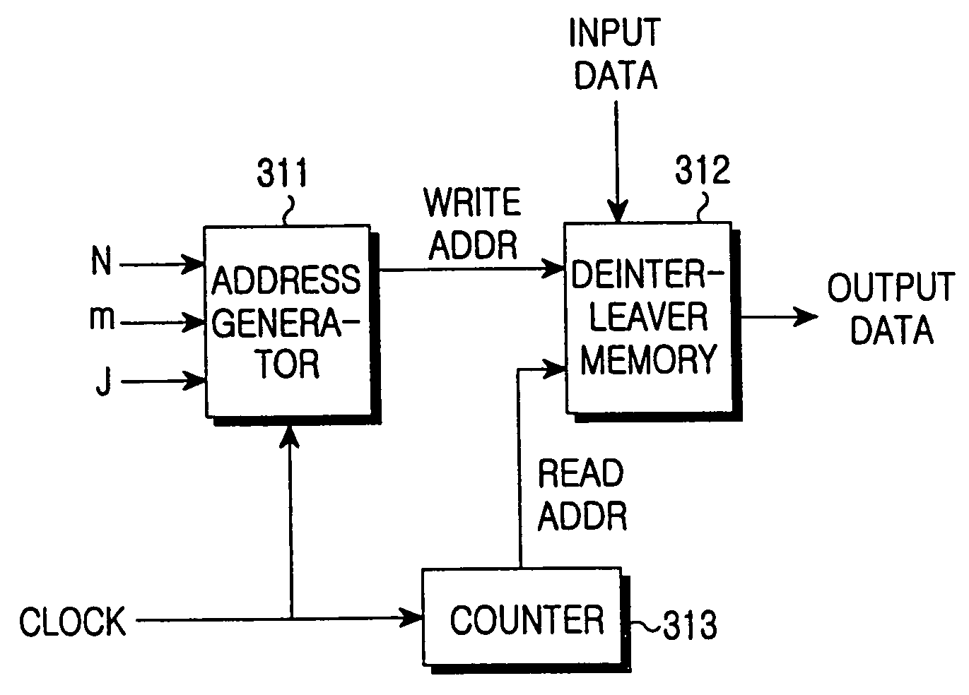
[0019]An interleaver / deinterleaver according to an embodiment of the present invention permutes the sequence of input symbols using an interleaving / deinterleaving algorithm and then stores them in an output buffer in a new sequence. Therefore, the interleaver / deinterleaver proposed by the invention comprises three parts: an interleaver memory (input data buffer and output data buffer), an address generator, and an existing counter.

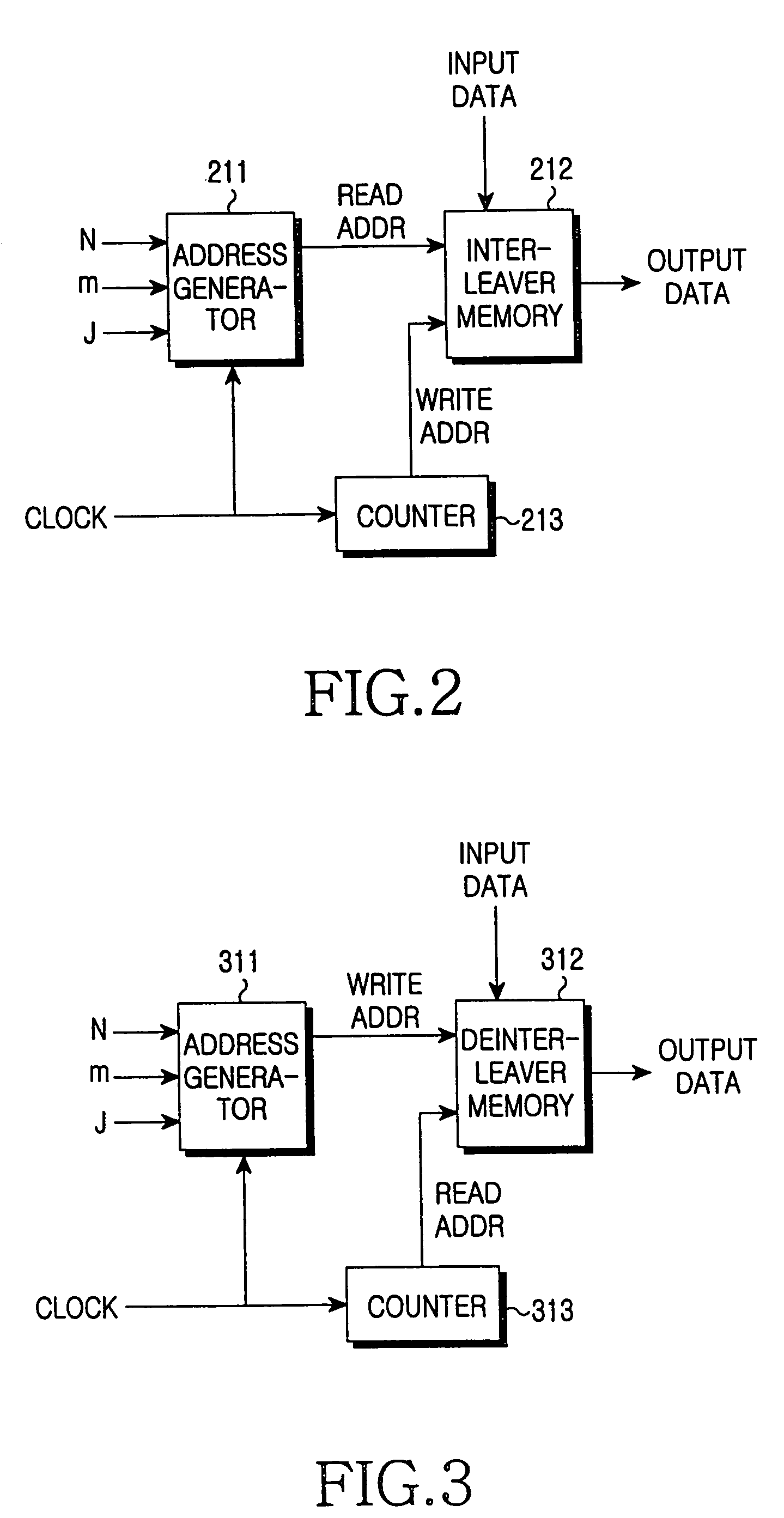
[0020]FIG. 2 shows an interleaver according to an embodiment of the present invention. Referring to FIG. 2, an address generator 211 receives an interleaver size value N, a first variable m, a second variable J and a clock, to generate an interleaver memory address for readi...


PUM


Abstract

A device for sequentially storing input bit symbols of a given interleaver size N in a memory at an address from 0 to N−1 and reading the stored bit symbols from the memory. The device comprises a look-up table for providing a first variable m and a second variable J satisfying the equation N=2m×J; and an address generator for generating a read address depending on the first and second variables m and J provided from the look-up table. The read address is determined by 2m(K mod J)+BROm(K / J), where K (0≦K≦(N−1)) denotes a reading sequence, BROm(y) is the bit-reversed m-bit value of y and / is a function in which a quotient of K divided by d is obtained, the quotient being an integer.

Description

PRIORITY[0001]This application is a continuation of application Ser. No. 10 / 744,752, filed Dec. 23, 2003 now abandoned, which is a continuation of application Ser. No. 09 / 459,051, filed Dec. 10, 1999, that issued on Dec. 23, 2003 as U.S. Pat. No. 6,668,350, which claims priority to an application filed in the Korean Intellectual Property Office on Dec. 10, 1998, and assigned Ser. No. 1998-54131, the contents of each of which are incorporated herein by reference.BACKGROUND OF THE INVENTION[0002]1. Field of the Invention[0003]The present invention relates generally to a communication system, and in particular, to an interleaving / deinterleaving device and method for a radio communication system.[0004]2. Description of the Related Art[0005]Interleaving is typically used in mobile communications to increase the performance of an error correction code in a fading channel, and is intimately associated with decoding of a random error correction code. Particularly, an air interface for an IM...

Claims


Application Information

Patent Timeline
Patent Type & Authority Patents(United States)
IPC IPC(8): G06F11/00H03M13/27H04B7/26G06F11/10H04L1/00
CPCH03M13/2703H03M13/2789H03M13/2764H03M13/275H04L1/00
Inventor KIM, MIN-GOO
Owner SAMSUNG ELECTRONICS CO LTD
Why Eureka
Try Eureka