Method of fabricating suspended beam in a MEMS process

a technology of suspended beams and manufacturing methods, applied in the field of inkjet printers, can solve problems such as failure to generate a bubble, difficulty in precisely matching the mask with the sides of the pit, and raised lip around the top

Inactive Publication Date: 2007-12-04
MEMJET TECH LTD
View PDF4 Cites 29 Cited by
  • Summary
  • Abstract
  • Description
  • Claims
  • Application Information

AI Technical Summary

Benefits of technology

[0060]Optionally, said photoresist is UV cured prior to deposition of said roof material, thereby preventing reflow of said photoresist during deposition.
[0088]Optionally, said photoresist is UV cured prior to deposition of said roof material, thereby preventing reflow of said photoresist during deposition.
[0111]Optionally, said photoresist is UV cured prior to deposition of said roof material, thereby preventing reflow of said photoresist during deposition.
[0128]Optionally, said wall projections are positioned for minimizing color-mixing of inks on said nozzle plate.

Problems solved by technology

However, it is difficult to precisely match the mask with the sides of the pit.
The stringers can short circuit the heater so that it fails to generate a bubble.
Unfortunately, this produces a raised lip around top of the trench.
These hotspots affect the operation of the heater and typically reduce heater life.

Method used


Image

  • Method of fabricating suspended beam in a MEMS process
  • Method of fabricating suspended beam in a MEMS process
  • Method of fabricating suspended beam in a MEMS process

Examples


Embodiment Construction

[0195]In the description than follows, corresponding reference numerals relate to corresponding parts. For convenience, the features indicated by each reference numeral are listed below.

MNN MPN SERIES PARTS LIST

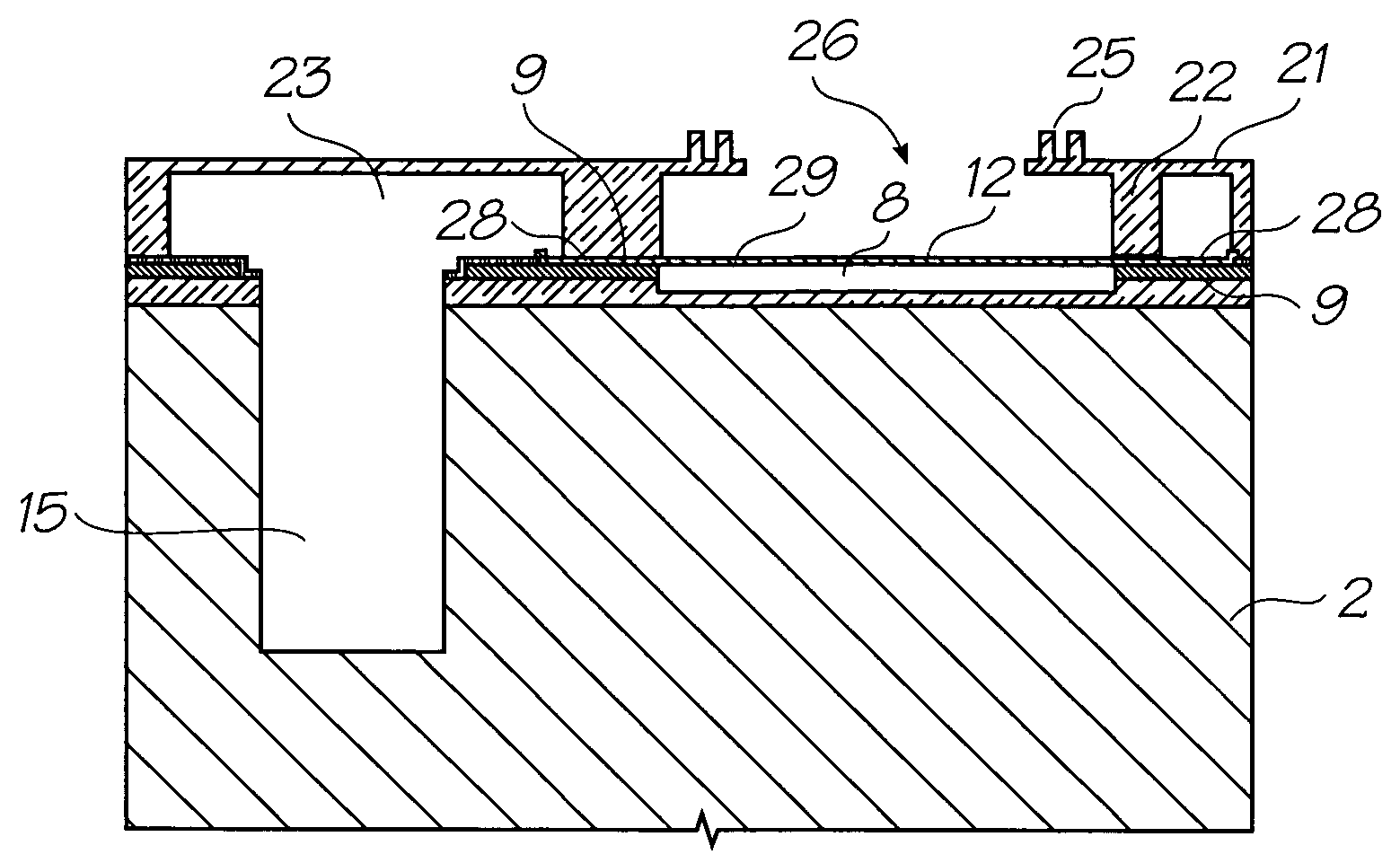
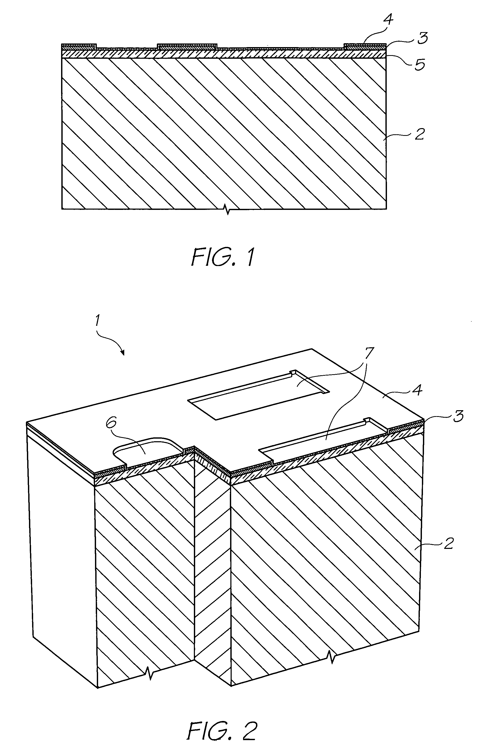
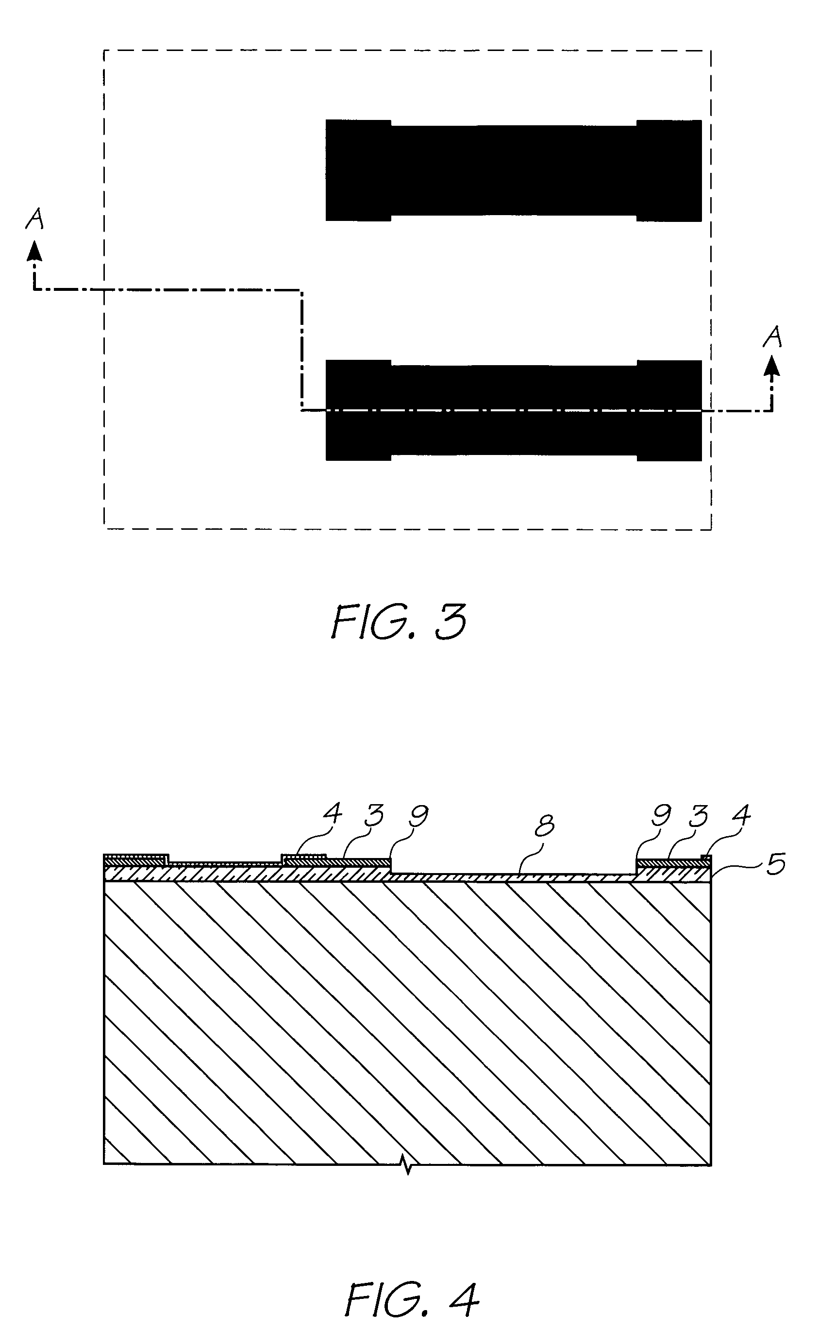
[0196]1. Nozzle Unit Cell[0197]2. Silicon Wafer[0198]3. Topmost Aluminium Metal Layer in the CMOS metal layers[0199]4. Passivation Layer[0200]5. CVD Oxide Layer[0201]6. Ink Inlet Opening in Topmost Aluminium Metal Layer 3.[0202]7. Pit Opening in Topmost Aluminium Metal Layer 3.[0203]8. Pit[0204]9. Electrodes[0205]10. SAC1 Photoresist Layer[0206]11. Heater Material (TiAlN)[0207]12. Thermal Actuator[0208]13. Photoresist Layer[0209]14. Ink Inlet Opening Etched Through Photo Resist Layer[0210]15. Ink Inlet Passage[0211]16. SAC2 Photoresist Layer[0212]17. Chamber Side Wall Openings[0213]18. Front Channel Priming Feature[0214]19. Barrier Formation at Ink Inlet[0215]20. Chamber Roof Layer[0216]21. Roof[0217]22. Sidewalls[0218]23. Ink Conduit[0219]24. Nozzle Chambers[0220]25. Ellipti...


PUM


Abstract

A method of fabricating a suspended beam in a MEMS process, said method comprising the steps of:(a) etching a pit in a substrate, said pit having a base and sidewalls;(b) depositing sacrificial material on a surface of said substrate so as to fill said pit;(c) removing said sacrificial material from a perimeter region within said pit and from said substrate surface surrounding said pit;(d) reflowing remaining sacrificial material within said pit such that said remaining sacrificial material contacts said sidewalls;(e) depositing beam material on said substrate surface and on said reflowed sacrificial material; and(f) removing said reflowed sacrificial material to form said suspended beam.

Description

FIELD OF THE INVENTION[0001]The present invention relates to the field of inkjet printers and discloses an inkjet printing system using printheads manufactured with micro-electromechanical systems (MEMS) techniques.CO-PENDING APPLICATIONS[0002]The following applications have been filed by the Applicant simultaneously with the present application:[0003]11 / 24667611 / 24667711 / 24667811 / 24667911 / 24668011 / 24668111 / 24671411 / 24671311 / 24668911 / 24667111 / 24667011 / 24666911 / 24670411 / 24671011 / 24668811 / 24671611 / 24671511 / 24670711 / 24670611 / 24670511 / 24670811 / 24669311 / 24669211 / 24669611 / 24669511 / 24669411 / 24668711 / 24671811 / 24668511 / 24668611 / 24670311 / 24669111 / 24671111 / 24669011 / 24671211 / 24671711 / 24670911 / 24670011 / 24670111 / 24670211 / 24666811 / 24669711 / 24669811 / 24669911 / 24667511 / 24667411 / 24666711 / 24667211 / 24667311 / 24668311 / 246682[0004]The disclosures of these co-pending applications are incorporated herein by reference.CROSS REFERENCES TO RELATED APPLICATIONS[0005]Various methods, systems and apparatus relatin...

Claims


Application Information

Patent Timeline
Patent Type & Authority Patents(United States)
IPC IPC(8): H01L21/00
CPCB41J2/1404B41J2/1601B41J2/1628B41J2/1631B41J2/1639B81C1/00142B41J2/1645B41J2/1642B41J2002/14403B41J2002/14475B41J2202/11B81B2201/052
Inventor SILVERBROOK, KIA
Owner MEMJET TECH LTD
Why Eureka
Try Eureka