Power generating system and its control method

a power generation system and control method technology, applied in the direction of dynamo-electric converter control, dynamo-electric gear control, greenhouse gas reduction, etc., can solve the problems of deterioration in reliability, increase in cost, deterioration in reliability, etc., and achieve stable micro adjustment, maximum efficiency, and fast transient response characteristic

Inactive Publication Date: 2007-12-04
YASKAWA DENKI KK
View PDF57 Cites 27 Cited by
  • Summary
  • Abstract
  • Description
  • Claims
  • Application Information

AI Technical Summary

Benefits of technology

[0008]An object of the present invention is to provide a power generation system and a control method thereof, in which it is possible to accomplish high reliability, simplification of circuits, and reduction of cost by acquiring speed information from a generator without using a speed sensor for detecting a shaft speed of a turbine. Another object of the present invention is to realize high-efficiency operation without using means for detecting an energy quantity of a dynamic power source, such as a wind speed sensor.
[0011]According to the present invention, since the induced voltage or the rotor magnetic flux is calculated from the output voltage and the output current of the generator, the shaft speed of the generator is estimated from the phase of the induced voltage or the phase of the rotor magnetic flux, and the output of the turbine is calculated from the estimated shaft speed value and the output of the generator, it is possible to calculate the output of the turbine without using a speed sensor for detecting the shaft speed of the generator and thus to accomplish simplification of circuits, reduction in cost, and high reliability.
[0016]According to the present invention, since the micro speed instruction is calculated from the output variation of the turbine and is added to the speed instruction, it is possible to obtain both the fast transient response characteristic and the stable micro adjustment and it is thus possible to always obtain the maximum efficiency when design values and actual values are different from each other.

Problems solved by technology

As a result, when the distance from the speed sensor 8 to the power controller 95 is increased, the wire should be elongated, thereby causing a problem with deterioration in reliability due to disconnection of the wire, etc.
In addition, since the speed sensor is always rotated during rotation of the windmill, the lifetime of the speed sensor per se causes the problem with deterioration in reliability.
The installation of the speed sensor also causes a problem with increase in cost.
Although the wind-power generation system employing the windmill as a turbine has been described here, the same problems may be caused in power generation systems for generating electric power by converting dynamic energy into rotational energy using a turbine other than the windmill.

Method used


Image

  • Power generating system and its control method
  • Power generating system and its control method
  • Power generating system and its control method

Examples


embodiment 1

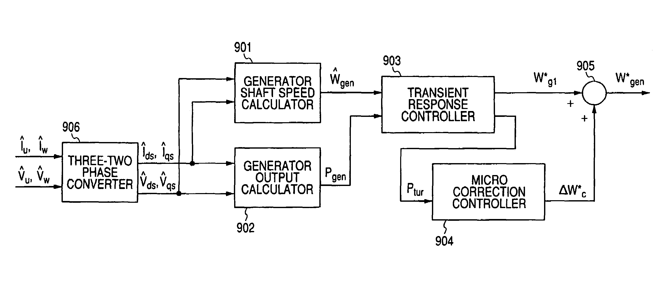
[0084]Next, an example of a specific construction of the generator shaft-speed calculator 901 is shown in FIG. 6. In the example shown in FIG. 6, the generator shaft-speed calculator 901 includes an induced voltage detector 402, a phase detector 403, and a differentiator 404. This example corresponds to Embodiment 1 of the speed estimation described above.

[0085]The induced voltage detector 402 detects the induced voltage

Êds,Êqs

from the two-phase current and the two-phase voltage from the three-two phase converter 906 by using Equation 21 described above.

[0086]The phase detector 403 detects the phase of the induced voltage

{circumflex over (θ)}e

from the induced voltage detected by the induced voltage detector 402 using Equation 23 described above.

[0087]The differentiator 404 calculates the estimated shaft speed value which is the rotational speed of the induced voltage, that is, the estimated shaft speed value of the generator 3 by differentiating the estimated phase value of the indu...

embodiment 2

[0088]Another example of the specific construction of the generator shaft-speed calculator 901 shown in FIG. 5 is illustrated in FIG. 7. In the example shown in FIG. 7, the generator shaft-speed calculator 901 includes a rotor magnetic-flux detector 502, a phase detector 503, and a differentiator 504. This example corresponds to Embodiment 2 of speed estimation described above.

[0089]The rotor magnetic-flux detector 502 detects the rotor magnetic flux

{circumflex over (Φ)}d,{circumflex over (Φ)}q

from the two-phase current

Îds,Îqs

and the two-phase voltage

{circumflex over (V)}ds,{circumflex over (V)}qs

which are converted into the stationery d-q coordinate system by the three-two phase converter 906 shown in FIG. 5 using Equation 25 described above.

[0090]The phase detector 503 detects the phase of the rotor magnetic flux

{circumflex over (θ)}Φ

from the rotor magnetic flux detected by the rotor magnetic-flux detector 502.

[0091]The differentiator 504 calculates the estimated rotational speed ...


PUM


Abstract

A power controller 5 calculates the induced voltage or rotor magnetic flux from the output voltage and the output current of a generator 3, estimates a shaft speed of the generator 3 from the phase of the induced voltage or the phase of the rotor magnetic flux, and calculate the output of a windmill 1 from the estimated value of the shaft speed and the output of the generator 3. As a result, since the output of the windmill 1 can be calculated without requiring a speed sensor for detecting the shaft speed of the generator 3, it is possible to accomplish simplification of circuits, reduction of cost, and high reliability.

Description

TECHNICAL FIELD[0001]The present invention relates to a control method of a power generation system for generating electric power by converting dynamic energy such as wind power or water power into rotational energy, in which a generator can be operated with the maximum efficiency.RELATED ART[0002]As an example of a conventional power generation system, a structure of a conventional wind-power generation system is shown in FIG. 1. The conventional wind-power generation system includes a windmilll, a gear / coupling 2 for changing and delivering a shaft speed of the windmilll, a generator 3, a power converter 4, a power controller 95, and a speed sensor 8, and supplies the generated power to a load 6.[0003]Next, operations of the conventional wind-power generation system are described. The wind energy obtained from the rotation of the windmill 1 is subjected to the change of the shaft speed by the gear / coupling 2 and then is delivered to the generator. The generator 3 converts the wind...

Claims


Application Information

Patent Timeline
Patent Type & Authority Patents(United States)
IPC IPC(8): H02P9/00F03D7/00H02P9/10H02P9/14F03B15/08F03B15/16F03D7/04F03D9/00H02P9/04H02P9/48H02P21/14
CPCH02P9/009H02P2203/09Y02E10/725Y02E10/723Y02E10/226Y02E10/20Y02E10/72
Inventor KANG, JUNKOOHAYASHI, SAEMITSUMORIMOTO, SHINYA
Owner YASKAWA DENKI KK
Why Eureka
Try Eureka