Boost circuit capable of step-up ratio control

a voltage generating apparatus and step-up technology, applied in the direction of cycle equipment, pulse technique, instruments, etc., can solve the problems of improper equipment operation, adversely affecting the reliability of the power supply apparatus itself or equipment, and excessive current may temporarily flow, so as to reduce the resistance between the voltage input terminal and the voltage output terminal. , the effect of power loss

Active Publication Date: 2007-12-04
ROHM CO LTD
View PDF2 Cites 47 Cited by
  • Summary
  • Abstract
  • Description
  • Claims
  • Application Information

AI Technical Summary

Benefits of technology

[0010]According to this aspect, the voltage fed to the input terminal of the boost circuit is directly output to the output terminal thereof so that power loss is reduced.
[0026]The present invention according to yet another aspect provides an electronic apparatus. The electronic apparatus according to this aspect comprises: a regulator circuit to which a voltage is applied from a given power supply; a boost circuit which boosts an output from the regulator circuit; a load which is driven by an output of the boost circuit; and a switch which, under a predetermined condition, forms a path that skips a voltage-related operation by the regulator circuit and the boost circuit and that applies the voltage from the power supply directly to the load. The phrase “given power supply” refers, for example, to a battery. The electronic apparatus may be a cell phone, for example. According to this aspect, the voltage fed from the given power is directly applied to the load so that power loss is reduced.

Problems solved by technology

However, an excessive current may temporarily flow due to initial charge built up in the boost capacitors.
An inrush current may adversely affect the reliability of a power supply apparatus itself or equipment including the power supply apparatus.
It may also induce improper operation of the equipment.

Method used


Image

  • Boost circuit capable of step-up ratio control
  • Boost circuit capable of step-up ratio control
  • Boost circuit capable of step-up ratio control

Examples


Embodiment Construction

[0038]The invention will now be described based on preferred embodiments which do not intend to limit the scope of the present invention but exemplify the invention. All of the features and the combinations thereof described in the embodiment are not necessarily essential to the invention.

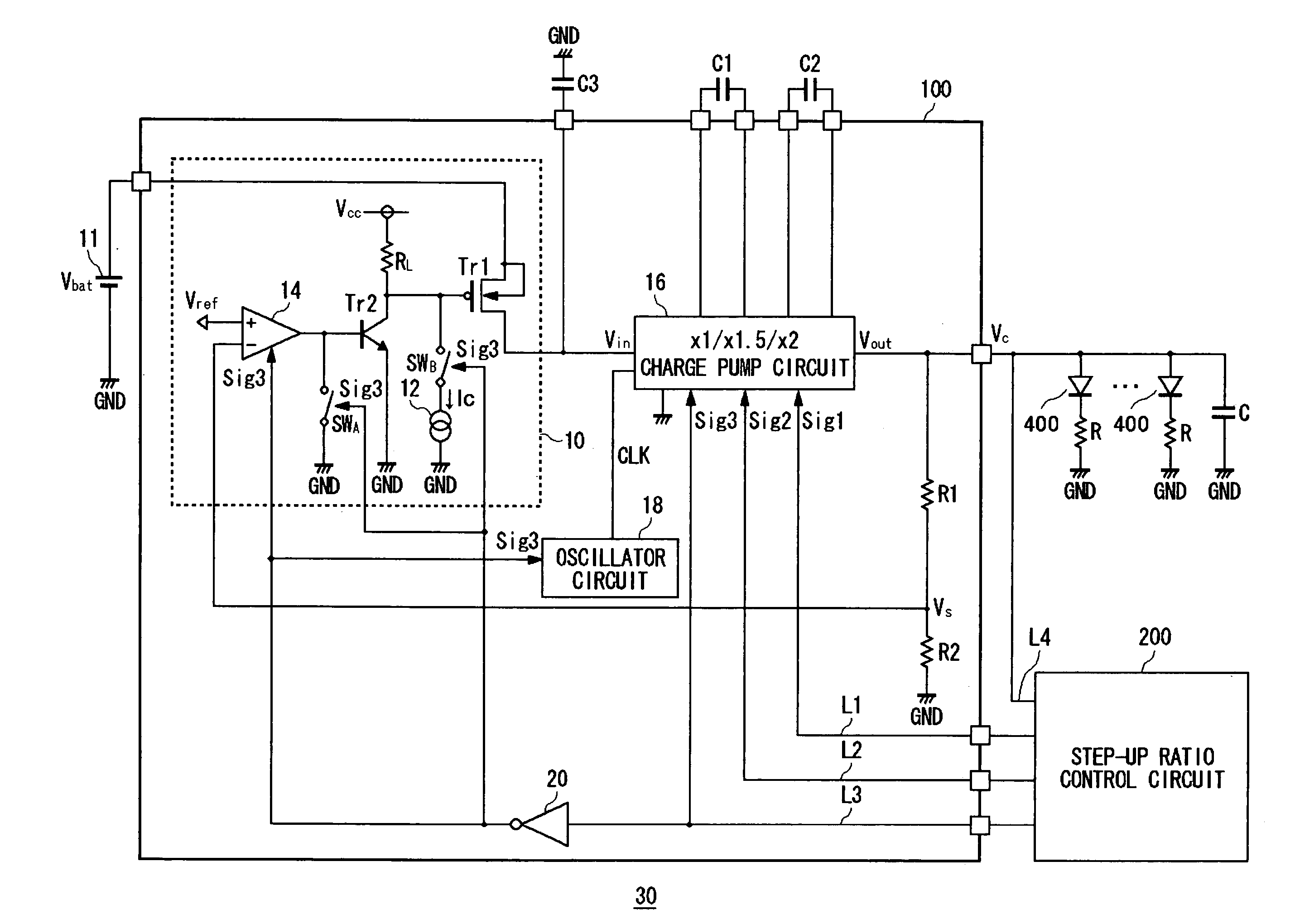
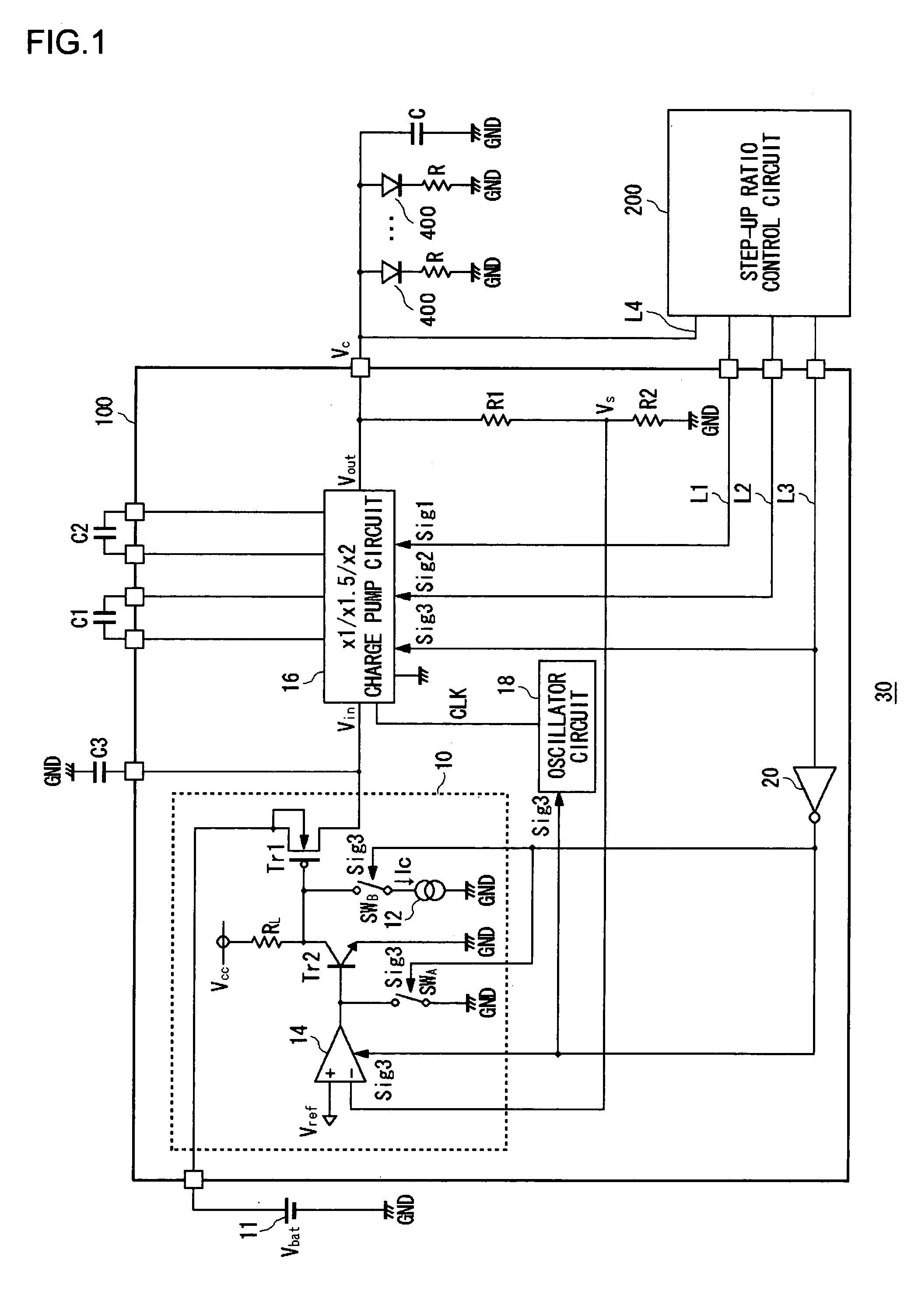
[0039]A summary of an embodiment of the present invention will be given. The voltage generating apparatus according to the embodiment is used in electronic apparatuses including battery-driven portable equipment such as cell phones and PDAs. A drive voltage, obtained by boosting the battery voltage of a lithium ion battery or the like, is supplied to LEDs used as backlight provided in the portable equipment. The life of a battery built in the portable equipment is limited. In order to extend the life, current consumption should preferably be reduced. The voltage generating apparatus according to the embodiment achieves reduced power consumption by reducing consumption current flowing in the circuit...


PUM


Abstract

When a step-up ratio control circuit sets a step-up ratio of a charge pump circuit to 1.0 to enable a short mode, a path inside the charge pump circuit is short-circuited and a first transistor is completely turned on. This produces an inrush current derived from a battery voltage of a lithium ion battery flowing into the charge pump circuit. To address this, a constant current circuit is operated so that the first transistor is turned on slowly. Further, the operation of an oscillator and an operational amplifier is suspended when the short mode is enabled.

Description

BACKGROUND OF THE INVENTION[0001]1. Field of the Invention[0002]The present invention relates to a boost circuit and a voltage generating apparatus and an electronic apparatus in which the boost circuit can be used.[0003]2. Description of the Related Art[0004]Battery-driven portable equipment such as a portable telephone and a personal data assistant (PDA) use light-emitting diodes (LED) for a variety of purposes. For example, LEDs are used to provide backlight for a liquid crystal display (LCD) or an electronic flash light for a charge-coupled device (CCD) camera. LEDs emitting different colors are operated to blink for illumination. In order to drive an LED, the battery voltage of about 3.6V of, for example, a lithium ion battery should be boosted to about 4.5V as a drive voltage. When the battery voltage drops due to battery consumption, or when a load current flowing in the LEDs is increased, causing an increased voltage drop, the battery voltage should be boosted by a higher st...

Claims


Application Information

Patent Timeline
Patent Type & Authority Patents(United States)
IPC IPC(8): H02M3/18H02M7/00G05F1/56H02M3/00H02M3/07H02M3/335
CPCH02M3/07B62M1/18B62M1/12B62J1/06A63B69/04A63B23/035
Inventor ITO, TOMOYUKIYAMAMOTO, ISAO
Owner ROHM CO LTD
Why Eureka
Try Eureka