Storm barrier assembly

a technology of storm barriers and assemblies, which is applied in the direction of wing arrangements, mechanical devices, shutters/movable grilles, etc., can solve the problems of high wind and airborne debris, catastrophic failure of roof structures, and high cost of shutters and other permanently installed devices, and achieve the effect of low surface friction

Inactive Publication Date: 2007-12-11
TEMERITY CREATIVE
View PDF45 Cites 32 Cited by
  • Summary
  • Abstract
  • Description
  • Claims
  • Application Information

AI Technical Summary

Benefits of technology

[0010]An apparatus and assembly for retaining a substantially flat, protective panel within a frame such as a window frame are disclosed herein. In one embodiment, the panel retention apparatus of the present invention includes a bracket member for fitting over an edge of the panel, such that the bracket member provides edge and lateral support for the panel. The apparatus further includes a rack and gear mechanism affixed to the bracket member. The rack and gear mechanism preferably includes a circular driving gear and a rack member having a foot member attached at one end and further having a rack gear engaging the circular driving gear such that the rack member is linearly movable with respect to the bracket member responsive to rotational actuation of the circular driving gear. In a preferred embodiment, the rack and gear mechanism components are fabricated of a Delrin composite material which provides a lightweight, corrosion resistant, and low surface friction actuation assembly.

Problems solved by technology

Glass doors and windows offer very little resistance to high winds and airborne debris.
The breaching of a building portal such as a glass door or window causes a dramatic pressure increase inside the structure resulting in a catastrophic failure of the roof structure.
While providing reliable storm protection, shutters and other permanently installed devices are expensive and are increasingly considered an unattractive feature on the exterior home or building décor.
A significant disadvantage of using temporary plywood panels is that it requires drilling or boring unsightly screw or nail holes in the frame structure surrounding the window to which the heavy cover panel is securely fastened.
Given the natural reluctance of home and building owners to damage their outside property with such boreholes in the absence of dire necessity, many persons find themselves hurriedly attempting to install such panels in the period immediately prior to a forecasted storm.
Under time pressures and possibly low light, or increasingly windy or otherwise hostile weather conditions, the installation of plywood panels over doors and windows is often haphazard, resulting in compromised barrier integrity and / or excessive damage to the window or door frames to which the panels are secured.
Other drawbacks of using plywood panels include the considerable weight of large panels which further require storage and protection from moisture and wood-destroying insects.
A critical drawback in using the window protection device disclosed in U.S. Pat. No. 6,219,978 is that actuation of the slide-arm-and-bolt assembly described therein requires significant hand tool working, resulting in a relatively slow and cumbersome panel installation process.
When installing a panel using such a device, for example, the helical extension and retraction of the extender bolt requires tool actuation in a rotational plane transverse to the panel surface plane and is therefore time consuming and inefficient in terms of obstructing the user's ability to quickly adjust to the correct tension by hand feel in the limited working volume adjacent the panel.
While eliminating the aforementioned drawbacks of the devices disclosed in U.S. Pat. No. 6,219,978, the obvious problem with this solution is the lack of means for selectively adjusting the pressure applied by the spring tensioned stoppers.

Method used


Image

  • Storm barrier assembly
  • Storm barrier assembly
  • Storm barrier assembly

Examples


Embodiment Construction

[0021]The present invention is described in a preferred embodiment in the following description with reference to the figures. While this invention is described in terms of the best mode for achieving this invention's objectives, it will be appreciated by those skilled in the art that variations may be accomplished in view of these teachings without deviating from the spirit or scope of the present invention. Furthermore, when used and unless otherwise stated, the terms “horizontal,”“vertical,”“upper,”“lower,”“front,”“back,”“over,” and “under,” and similar position related terms are not to be construed as limiting the invention to a particular orientation. Instead, such terms are to be construed only on a relative basis with respect to the accompanying depicted embodiments.

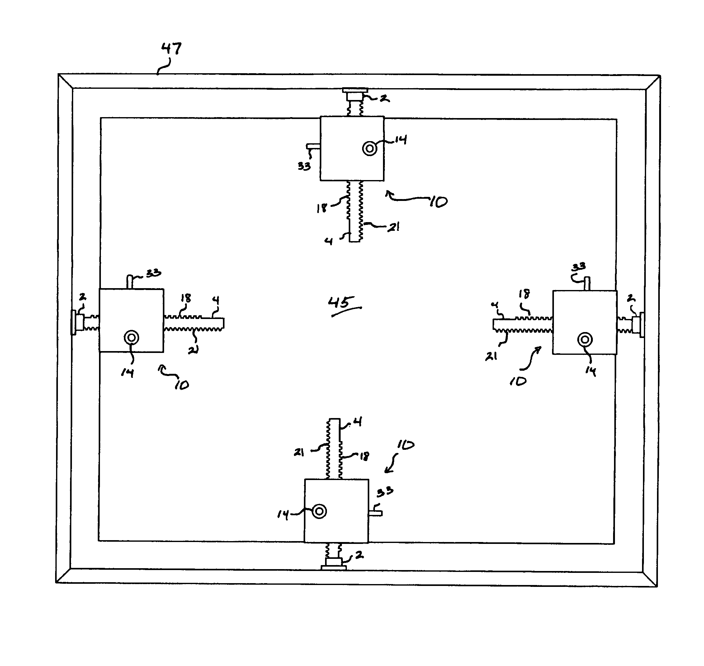
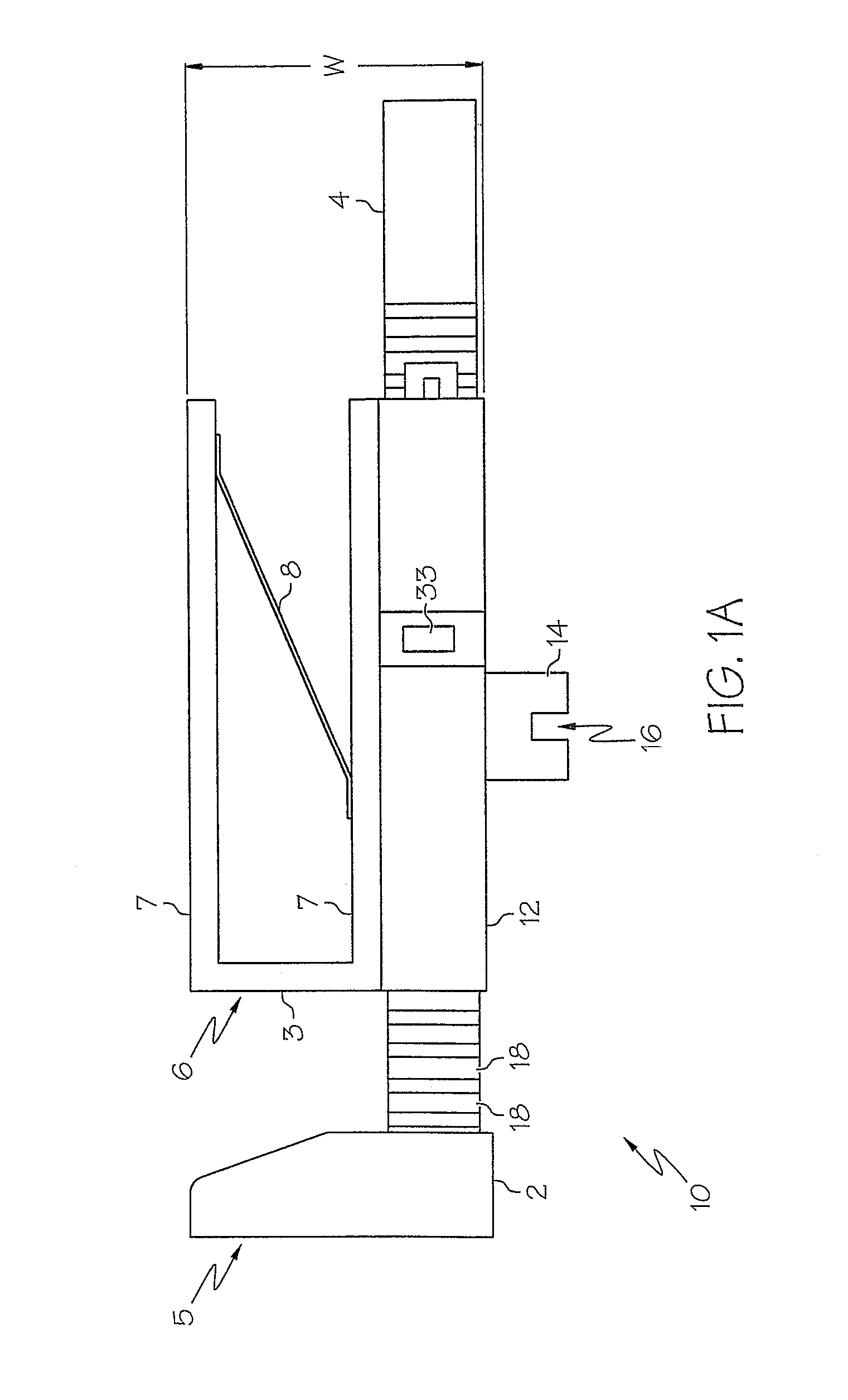
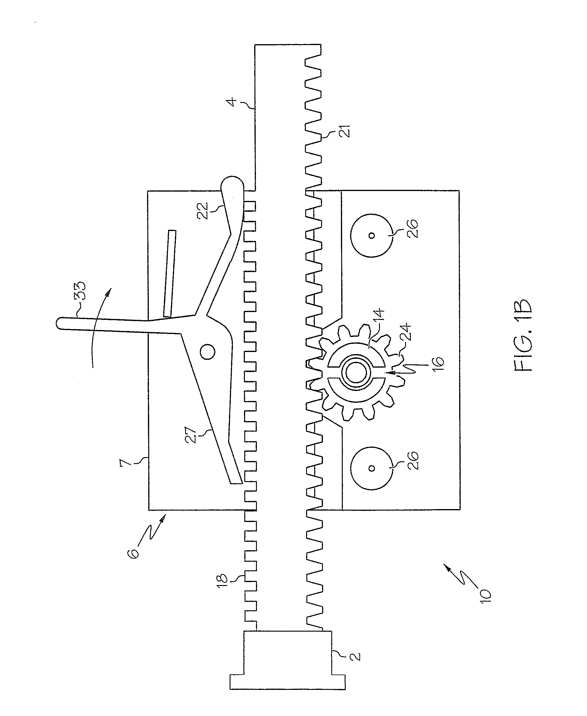
[0022]The present invention is directed to an improved method and apparatus for protectively covering a window or other framed building portal or entryway that is quickly and easily installable and provides adequa...


PUM


Abstract

An apparatus and assembly for retaining a substantially flat, protective panel within a frame such as a window frame. In one embodiment, the panel retention apparatus of the present invention includes a bracket member for fitting over an edge of the panel, such that the bracket member provides edge and lateral support for the panel. The apparatus further includes a rack and gear mechanism affixed to the bracket member. The rack and gear mechanism preferably includes a circular driving gear and a rack member having a foot member attached at one end and further having a rack gear engaging the circular driving gear such that the rack member is linearly movable with respect to the bracket member responsive to rotational actuation of the circular driving gear. In a preferred embodiment, the rack and gear mechanism components are fabricated of a Delrin composite material which provides a lightweight, corrosion resistant, and low surface friction actuation assembly.

Description

BACKGROUND OF THE INVENTION[0001]1. Technical Field[0002]The present invention relates generally to devices for suspending a panel within a frame, such as a window frame. In particular, the present invention relates to a protective panel apparatus that may be temporarily installed within a frame. More particularly, the present invention relates to a panel retention device and a panel assembly employing the same that provide a protective barrier against winds and other environmental hazards.[0003]2. Description of the Related Art[0004]Glass doors and windows offer very little resistance to high winds and airborne debris. The breaching of a building portal such as a glass door or window causes a dramatic pressure increase inside the structure resulting in a catastrophic failure of the roof structure. The continual and unpredictable threat posed by hurricanes, tornadoes and other severe weather phenomena resulting in property damage and injury or loss of life in many regions of the wor...

Claims


Application Information

Patent Timeline
Patent Type & Authority Patents(United States)
IPC IPC(8): E06B5/10E06B5/12
CPCE06B5/12E06B9/02Y10S52/12E06B2009/007Y10T292/1018Y10T292/202
Inventor CALFEE, AMY LYNN
Owner TEMERITY CREATIVE
Why Eureka
Try Eureka