Ejector

a technology of ejector and ejector plate, which is applied in the direction of machines/engines, refrigeration components, light and heating apparatus, etc., can solve the problems of not being able to achieve sufficient, and achieve the effect of improving cop and increasing performan

Active Publication Date: 2016-06-30
DENSO CORP
View PDF11 Cites 14 Cited by
  • Summary
  • Abstract
  • Description
  • Claims
  • Application Information

AI Technical Summary

Benefits of technology

[0008]However, according to examination of the inventors of the subject application, there is a case where, when the ejector-type refrigeration cycle of Patent Literature 1 is actually operated, a diffuser po

Problems solved by technology

However, according to examination of the inventors of the subject application, there is a case where, when the ejector-type refrigeration cycle of Patent Literature 1 is actually operated, a diffuser porti

Method used


Image

  • Ejector
  • Ejector
  • Ejector

Examples


first embodiment

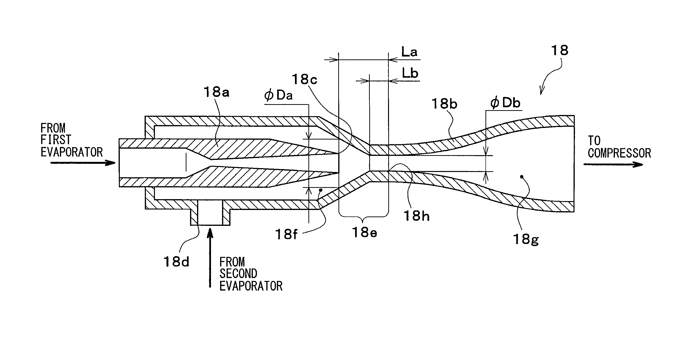
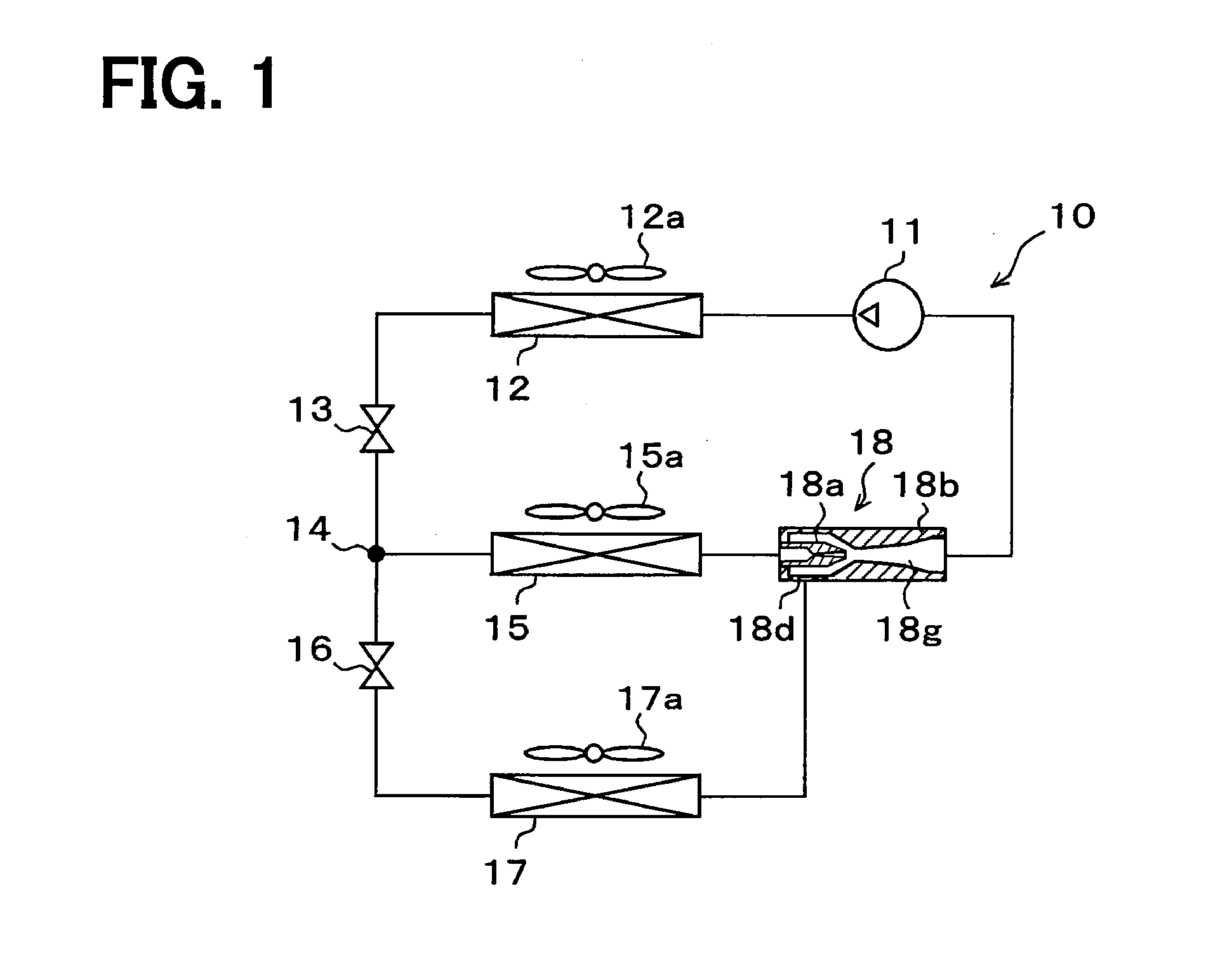
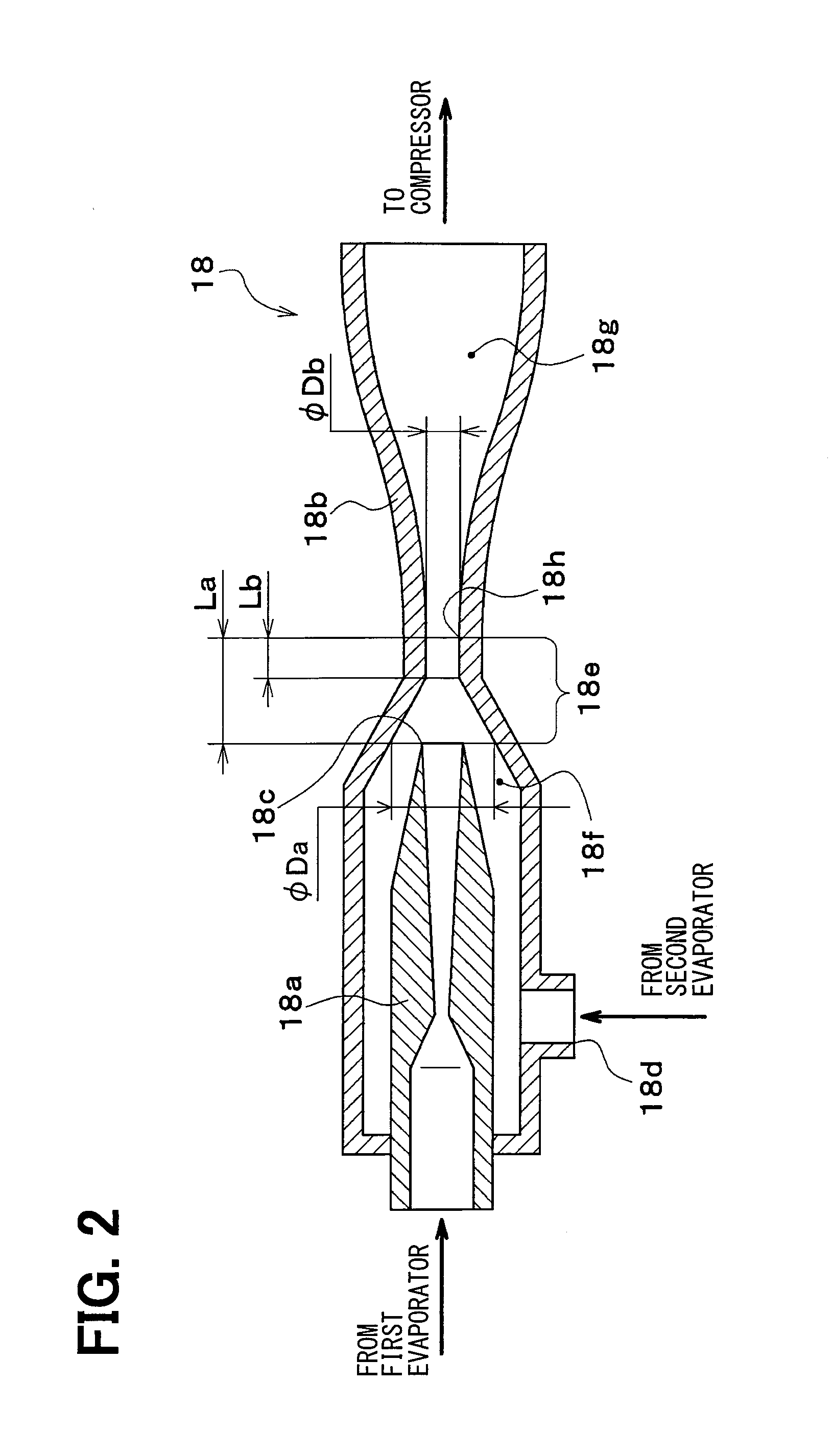
[0070]A description will hereinafter be made on a first embodiment by using FIG. 1 to FIG. 4. In this embodiment, an ejector-type refrigeration cycle 10 that includes an ejector 18 is used as a vehicular refrigeration cycle device. More specifically, the ejector-type refrigeration cycle 10 fulfills a function of cooling vehicle cabin inside air to be blown into a vehicle interior and a function of cooling box inside air to be blown into an in-vehicle refrigerator (i.e., cool box) arranged in the vehicle cabin.

[0071]In the ejector-type refrigeration cycle 10 depicted in an overall configuration diagram of FIG. 1, a compressor 11 draws a refrigerant, compresses the refrigerant until the refrigerant becomes a high-pressure refrigerant, and discharges the refrigerant. More specifically, the compressor 11 of this embodiment is an electric compressor that is configured by accommodating a fixed-capacity-type compression mechanism and an electric motor driving the compression mechanism in a...

second embodiment

[0125]In this embodiment, a description will be made on an example in which a configuration of an ejector 18 is changed as shown in FIG. 5 from that in the first embodiment. In FIG. 5 and other drawings, which will be described below, the same or equivalent portions to those in the first embodiment are denoted by the same reference signs.

[0126]More specifically, in the ejector 18 of this embodiment, a tapered section 18i, in which a refrigerant passage cross-sectional area gradually reduces toward a refrigerant injection port 18c, is formed as a refrigerant passage that is formed in a nozzle portion 18a. That is, the nozzle portion 18a of this embodiment is a so-called tapered nozzle. Furthermore, an injecting section 18j is formed on the lowermost downstream side of the refrigerant passage that is formed in the nozzle portion 18a of this embodiment.

[0127]The injecting section 18j is a space that guides the refrigerant from a downstream most portion of the tapered section 18i toward...

third embodiment

[0139]In this embodiment, a description will be made on an example in which a configuration of an ejector 18 is changed from that in the first embodiment as shown in FIG. 6, FIG. 7. More specifically, in the ejector 18 of this embodiment, a swirl space 18k, in which a refrigerant flowing thereinto from a refrigerant inlet port 18l swirls around an axis of a nozzle portion 18a, is provided on an upstream side, in the refrigerant flow direction, of a throat section (i.e., a minimum passage cross-sectional area section) of a refrigerant passage that is formed in the nozzle portion 18a.

[0140]In detail, the swirl space 18k is formed on the inside of a cylindrical section 18m that is provided on the upstream side in the nozzle portion 18a in the refrigerant flow direction. The cylindrical section 18m constitutes a swirl space forming member described in the claims. Thus, in this embodiment, the swirl space forming member and the nozzle portion are integrally configured.

[0141]The swirl sp...


PUM


Abstract

A mixing portion that is formed in an area from a refrigerant injection port of a nozzle portion to an inlet section of a diffuser portion in an internal space of a body portion of an ejector and that mixes an injection refrigerant injected from the refrigerant injection port and a suction refrigerant suctioned from a refrigerant suction port is provided. A distance from the refrigerant injection port to the inlet section in the mixing portion is determined such that a flow velocity of the refrigerant flowing into the inlet section of the diffuser portion becomes lower than or equal to a two-phase sound velocity. A shock wave that is generated at a time that a mixed refrigerant is shifted from a supersonic velocity state to a subsonic velocity state is generated in the mixing portion, so as to stabilize pressure increasing performance in the diffuser portion.

Description

CROSS REFERENCE TO RELATED APPLICATION[0001]This application is based on Japanese Patent Application No. 2013-127578 filed on Jun. 18, 2013, the disclosure of which is incorporated herein by reference.TECHNICAL FIELD[0002]The present disclosure relates to an ejector that decompresses a fluid and draws the fluid by a suction action of an injected fluid injected at a high velocity.BACKGROUND ART[0003]Conventionally, a vapor compressional refrigeration cycle device that includes an ejector (hereinafter referred to as an ejector-type refrigeration cycle) has been known.[0004]In this type of the ejector-type refrigeration cycle, a refrigerant flowing out of an evaporator is suctioned by an suction action of a high-velocity injection refrigerant injected from a nozzle portion of the ejector, pressure of a mixed refrigerant of the injection refrigerant and the suction refrigerant is increased by converting kinetic energy of the mixed refrigerant to pressure energy in a diffuser portion (i....

Claims


Application Information

Patent Timeline
IPC IPC(8): F04F5/20F25B5/02F25B41/00F04F5/46F25B1/08
CPCF04F5/20F04F5/46F25B5/02F25B41/00F25B1/08F25B2341/0011
Inventor NISHIJIMA, HARUYUKIKAYANO, KENTATAKANO, YOSHIAKI
Owner DENSO CORP
Why Eureka
Try Eureka