
Self-cooling type air suspension air compressor with air storage function

A technology of air suspension and air compressor, which is applied in the direction of mechanical equipment, machine/engine, liquid fuel engine, etc. It can solve the problems of bearing or shaft damage, failure to form dynamic pressure air film, carbon deposition, etc., and achieve the goal of improving efficiency and stability Effect

Active Publication Date: 2018-11-09
BEIJING INSTITUTE OF PETROCHEMICAL TECHNOLOGY
View PDF5 Cites 12 Cited by
  • Summary
  • Abstract
  • Description
  • Claims
  • Application Information

AI Technical Summary

Problems solved by technology

Due to the start-stop stage of the compressor, the rotation speed of the rotating shaft decreases and the wedge-shaped action cannot form an effective dynamic pressure gas film that can support the suspension of the rotating shaft, which will cause surface contact between the rotating shaft and the dynamic pressure gas bearing to cause surface friction and generate a lot of heat. Carbon deposits will appear on the top foil of the air foil, which will cause damage to the bearing or shaft in the long run

Method used


Image

  • Self-cooling type air suspension air compressor with air storage function
  • Self-cooling type air suspension air compressor with air storage function

Examples


specific Embodiment approach

[0013] The self-cooling type air suspension compressor with gas storage function of the present invention, its preferred embodiment is:

[0014] Including combined compressor impeller, compressor volute, cooling turbine, heat pipe heat exchanger, DC brushless motor housing, compressor housing, DC brushless motor. The compressor impeller, cooling turbine, heat pipe heat exchanger, and air storage cavity are all installed at one end of the DC brushless motor. The DC brushless motor includes a stator, a rotor, and a rotor mandrel, and the rotor is coaxially connected with the combined compressor impeller and the cooling turbine through the rotor mandrel; the left side of the DC brushless motor is provided with a thrust bearing assembly, and the thrust bearing assembly includes The thrust bearing seat, the thrust disc, and a thrust bearing is arranged between the thrust bearing seat and the thrust disc. The thrust bearing is a foil type dynamic pressure gas thrust bearing. A rad...

specific Embodiment

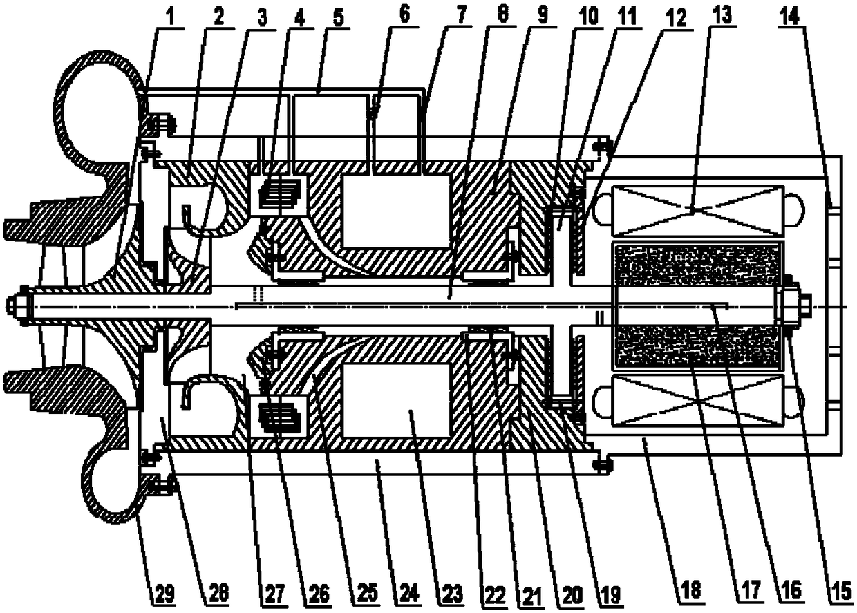
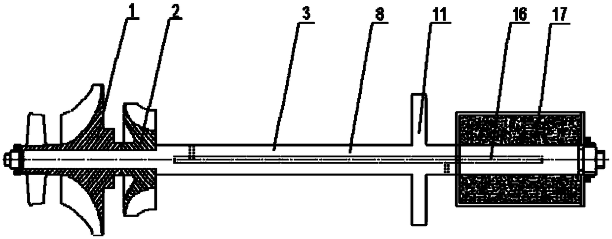
[0018] Such as figure 1 As shown, it includes combined compressor impeller 1, compressor volute 29, cooling turbine 3, heat pipe heat exchanger 4, air storage cavity 23, DC brushless motor housing 18, compressor housing 24, DC brushless motor . The compressor impeller, cooling turbine, heat pipe heat exchanger, and air storage cavity are all installed at one end of the DC brushless motor. The DC brushless motor includes a stator 13, a rotor 17, and a rotor mandrel 8, and the rotor is coaxially connected with the combined compressor impeller and the cooling turbine through the rotor mandrel; a thrust bearing assembly is arranged on the left side of the DC brushless motor, and the thrust The bearing assembly includes a thrust bearing seat and a thrust plate 11, and a thrust bearing 10 is arranged between the thrust bearing seat and the thrust plate. The thrust bearing is a foil type dynamic pressure gas thrust bearing. A radial bearing assembly is arranged inside the compress...


PUM


Abstract

The invention discloses a self-cooling type air suspension air compressor with an air storage function. The self-cooling type air suspension air compressor with the air storage function comprises a combined air compressor impeller, an air compressor volute, a cooling turbine, a heat pipe heat exchanger, an air storage cavity, an air bearing assembly, an air compressor shell and a direct current brushless motor. A rotor is coaxially connected with the combined air compressor impeller and the cooling turbine through a rotor core shaft. A thrust bearing assembly and a radial bearing assembly aresequentially arranged on the left side of the direct current brushless motor. The thrust bearing and the radial bearing are foil piece type hydrodynamic gas-lubricated bearings. According to the self-cooling type air suspension air compressor with the air storage function, high-pressure gas stored in the gas storage cavity is controlled to enter an air bearing assembly through the normally open electromagnetic valve during start-stop so as to prolong the time of a dynamic pressure gas film in the start-stop phase, thereby reducing the surface friction between the gas bearing and a rotating shaft to achieve the purpose of prolonging the service life of the gas bearing, and the self-cooling type air suspension air compressor with the air storage function has the advantages of large bearing capacity of the rotating shaft, less friction heat generation, more stable performance and the like by adopting a novel rotating shaft cooling mode.

Description

technical field [0001] The invention relates to an air suspension compressor, in particular to a self-cooling air suspension compressor with an air storage function. Background technique [0002] The centrifugal compressor is a type of compressor widely used, and the existing centrifugal compressor generally includes an impeller, a diffuser and a volute. Due to the high-speed rotation of the impeller, the gas enters the volute, and is discharged out of the volute after passing through the channel and the volute chamber, and the air is compressed through this process. The core equipment driving the rotation of the compressor is a DC brushless motor. The rotor shaft of the DC brushless motor is supported by radial bearings and thrust bearings. The friction and lubrication performance of the bearings are crucial to the performance of the compressor. Ball bearings have high friction and wear, short service life, and are not suitable for high-speed working conditions. The techno...

Claims


Application Information

Patent Timeline
Patent Type & Authority Applications(China)
IPC IPC(8): F04D25/06F04D29/58F04D29/056F04D27/00F04D29/28F04D29/08
CPCF04D25/06F04D27/004F04D29/056F04D29/083F04D29/284F04D29/5826
Inventor 肖云峰聂帅刘强孟波吕涛张志莲陈磊康宇轩冷雪
Owner BEIJING INSTITUTE OF PETROCHEMICAL TECHNOLOGY
Learn More