Method for producing a coplanar waveguide system on a substrate, and a component for the transmission of electromagnetic waves fabricated in accordance with such a method

a coplanar waveguide and substrate technology, applied in the direction of waveguides, waveguide type devices, waveguide details, etc., can solve the problems of low substrate loss, undesired effects such as emission, cross coupling of signals, oscillation of amplifier circuits, etc., and achieve simple grounding, reduced electrical losses, and improved stability

Inactive Publication Date: 2007-12-11
ATMEL CORP
View PDF5 Cites 16 Cited by
  • Summary
  • Abstract
  • Description
  • Claims
  • Application Information

AI Technical Summary

Benefits of technology

[0014]It is therefore an object of the present invention to provide a production method for micro-screened coplanar wave guides, and a component fabricated in accordance with such a method in order to eliminate the above-described disadvantages and in particular, to ensure a simpler and more cost-effective method as well as a component with lower electrical losses and simpler grounding.
[0015]The present invention is based on the idea that an improved integration of the individual conductors of the coplanar waveguide system and a direct connection of the upper and lower grounding points as well as an increased thickness of the individual conductors of the coplanar wave guide achieved in an uncomplicated manner, is ensured with the following steps: Construction of at least one coplanar waveguide system, preferably comprised of one signal conductor and two grounding conductors, on a predefined area of the substrate; forming a dielectric insulating layer over the individual conductors of the coplanar waveguide system; complete back-etching of an area of the substrate below the coplanar waveguide system beginning at the bottom side of the substrate in such a way that the signal conductor of the coplanar waveguide system is supported completely, and each grounding conductor is supported at least partially by embedding in the second dielectric insulating layer, while being freely suspended across the completely back-etched area of the substrate; and structured metallizing of the surface of the back-etched area of the substrate and of the segments of the individual conductors of the coplanar waveguide system located above the completely back-etched area, beginning at the bottom part of the substrate, for forming a signal conductor of increased thickness and grounding conductors of at least partially increased thickness.
[0016]By using this simple and cost-effective production method, a component for the transmission of electromagnetic waves is produced, whereby the conductors are completely protected from external influences without additional covering, and whereby the signal conductor is completely decoupled from the substrate such that no electromagnetic coupling with the substrate and, therefore, with other conductors, that is, other components, can occur. Thus, interferences and electromagnetic losses can be reduced or entirely eliminated.

Problems solved by technology

The disadvantage of this conventional approach, however, has proven to be the fact that by direct coupling of the coplanar wave-guide system, that is, the individual conductors of the coplanar wave guide with the dielectric layer, that is, the substrate, high line transmission losses, high substrate losses and minimal muting of the interactions of the individual modes with each other occur.
Thus, undesired effects like emission, cross coupling of signals, or oscillations of amplifier circuits etc. occur, particularly in the high frequency field.
The disadvantage of this conventional approach, however, has proven to be the fact that the conventional fabrication of a micro-screened coplanar wave guide depends on the technology for the fabrication of the thin dielectric membrane and also on the anisotropic etching process of the carrier substrate.
The production method of such a three-layer-construction is costly and complicated and requires at least two steps.
Thus, this production method is labor-intensive and costly, whereby the metallizations can only be made relatively thin resulting in high line transmission losses and high electrical resistance values.
In addition, this conventional approach has the disadvantage that the upper grounding points and the lower mass conductors are not directly interconnected but are separated from one another by a dielectric layer.
Thus, the individual grounding points have to be grounded separately from one another, which requires additional expenditure in labor.

Method used


Image

  • Method for producing a coplanar waveguide system on a substrate, and a component for the transmission of electromagnetic waves fabricated in accordance with such a method
  • Method for producing a coplanar waveguide system on a substrate, and a component for the transmission of electromagnetic waves fabricated in accordance with such a method
  • Method for producing a coplanar waveguide system on a substrate, and a component for the transmission of electromagnetic waves fabricated in accordance with such a method

Examples


first embodiment

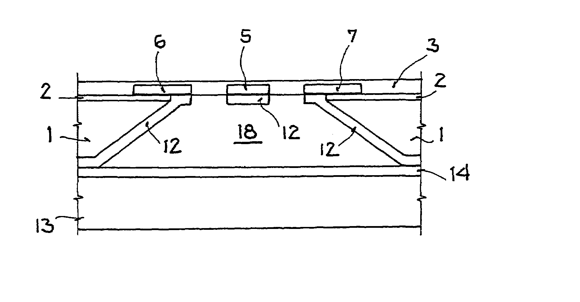
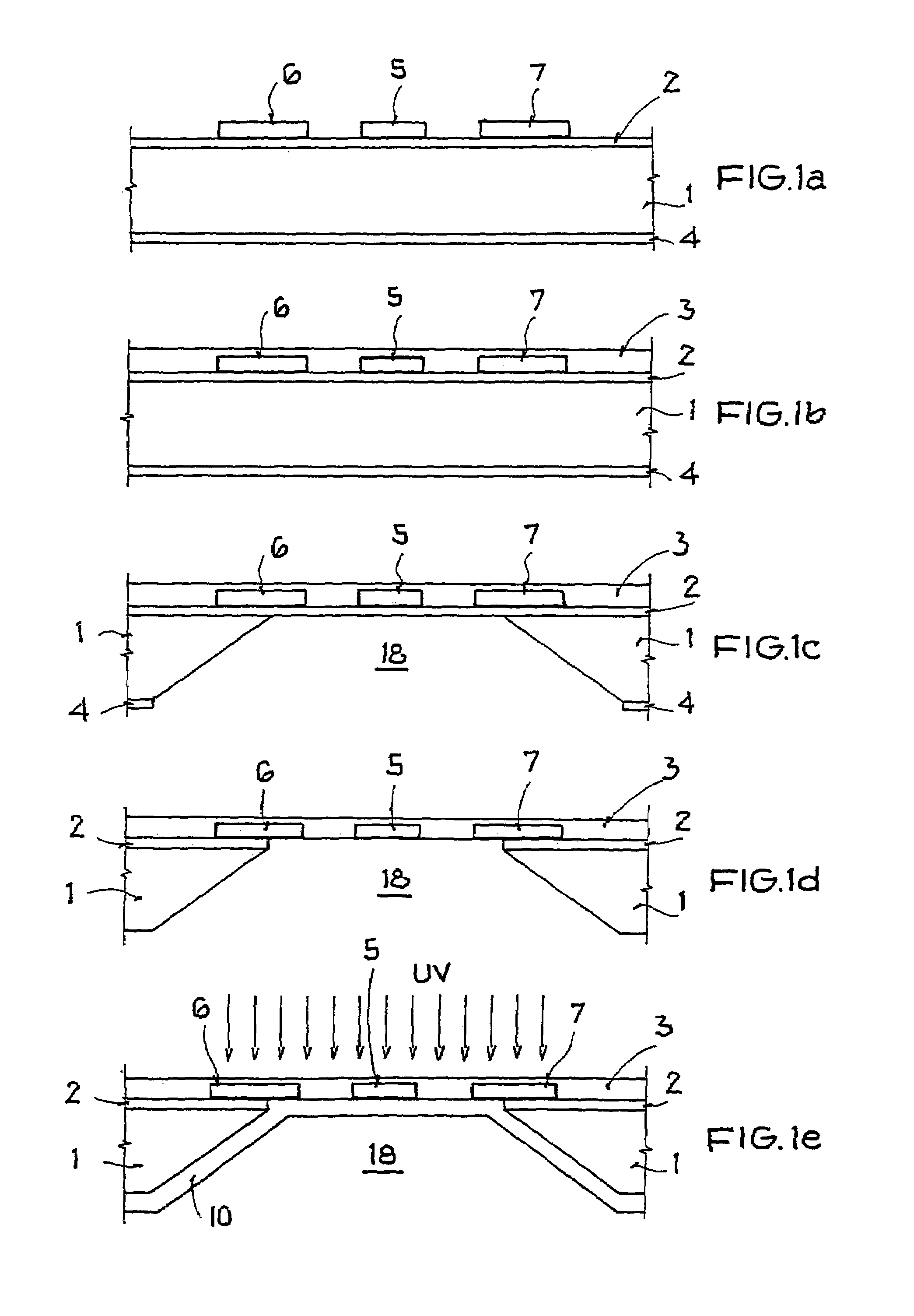
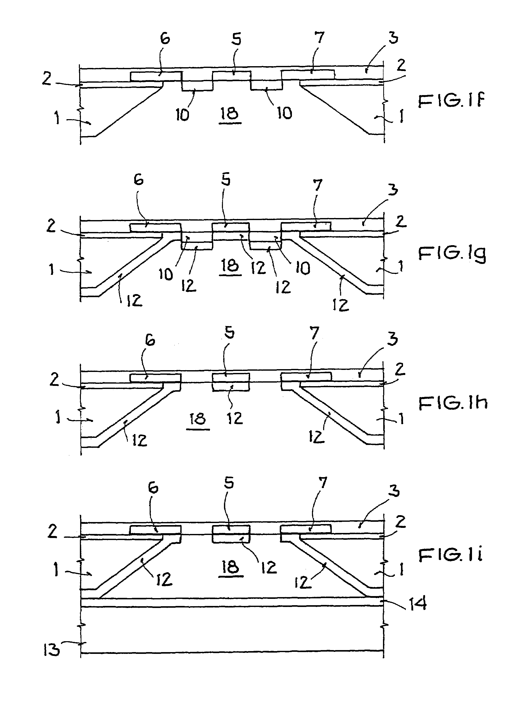
[0042]FIGS. 1a to 1i illustrate cross-sectional views of a component in individual method stages, whereby in FIGS. 1a to 1i, the production method of a component for the transmission of electromagnetic waves according to the present invention is described in detail.

[0043]As is shown in FIG. 1a, in a known method step for producing a finite ground coplanar wave guide (FGCPW), for example, the top side and the bottom side of a substrate 1 are provided with a first dielectric insulating layer 2, that is, with an additional dielectric insulating layer 4 (henceforth referred to as third insulation layer 4), which in certain instances can also be omitted. The substrate 1 is, for example, a low-resistance silicon semiconductor substrate, or the like. The first and third dielectric insulating layer 2, or 4, can be formed as an approximately 1-2 μm-thick silicon nitride or silicon dioxide layer, for example. Subsequently, a signal conductor 5 and two grounding conductors 6 and 7 are metalliz...

second embodiment

[0059]Due to the anisotropic back-etching of the substrate 1, as previously described, the oblique-shaped boundary area of the back-etched area 18 is formed. Therebelow, with reference to FIGS. 2a to 2k, a production method according to the present invention is described, whereby the geometric limitations based on the diagonally back-etched areas 18 are reduced and adjacent coplanar waveguide systems can be arranged in closer proximity to one another without diminishing the mechanical stability of the component. With the below-described method, shielding hollow cavities with a higher integration density can be formed below the coplanar waveguide system without adding mechanical instability to the surface of the component.

[0060]As can be seen in FIG. 2a, analogous to the first embodiment in a method step for the production of a finite ground coplanar waveguide (FGCPW), for example, a substrate 1 is provided on its top and bottom sides with a first dielectric insulating layer 2, that ...

fifth embodiment

[0086]FIG. 5 illustrates a cross-sectional view of the component according to the present invention. As is shown in FIG. 5, a covering metallization 16 is additionally formed over the coplanar waveguide system, whereby the respective rim regions of the covering metallization 16 are connected with the outer areas of the two grounding conductors 6 and 7. In this way, a closed system to protect the signal conductor from external interferences and dirt is constructed. In addition, the covering metallization 16 is thus arranged for a common electrical connection of all grounding conductors so that only a common mass connection is required.


PUM

PropertyMeasurementUnit
transmissionaaaaaaaaaa
areaaaaaaaaaaa
dielectricaaaaaaaaaa

Abstract

A component for the transmission of electromagnetic waves and a method for producing such a component is provided, whereby conductors of a coplanar waveguide system are embedded in a membrane such that they are at least partially suspended across a back-etched area of the substrate for the decoupling of the conductors from the substrate (1). An additional substrate is connected to the bottom side of the back-etched area of the substrate in such a way that a hollow cavity is formed.

Description

[0001]This nonprovisional application claims priority under 35 U.S.C. § 119(a) on German Patent Application No. DE 102004022177.4, which was filed in Germany on May 5, 2004, and which is herein incorporated by reference.BACKGROUND OF THE INVENTION[0002]1. Field of the Invention[0003]The present invention relates to a method for producing a coplanar waveguide system on a substrate for the transmission of electromagnetic waves and a component fabricated in accordance with such a method.[0004]2. Description of the Background Art[0005]With increasing operating frequency, component modeling of components integrated on a semiconductor substrate is playing an increasingly bigger role because it causes transmission-line characteristics, reflections on discontinuities, overlapping and dissipation to increase. That makes it generally imperative to consider these effects in the modeling process, particularly in the high frequency field. Particularly with a low-resistance substrate, for example...

Claims


Application Information

Patent Timeline
Patent Type & Authority Patents(United States)
IPC IPC(8): H01P3/08B81C1/00B82B1/00H01L21/768H01L23/66H01P11/00
CPCH01P11/003
Inventor JOODAKI, MOJTABA
Owner ATMEL CORP
Why Eureka
Try Eureka