
Transflective liquid crystal display device with particular angle relationships between the half wave plate and polarizers

a liquid crystal display and half wave plate technology, applied in static indicating devices, instruments, non-linear optics, etc., can solve the problems of inefficient optical modulation, flat panel display is beginning to appear, and tft-lcd only employs 3 8% of incident light generated, etc., to achieve the effect of increasing brightness and efficiency

Inactive Publication Date: 2007-12-11
LG DISPLAY CO LTD
View PDF16 Cites 0 Cited by
  • Summary
  • Abstract
  • Description
  • Claims
  • Application Information

AI Technical Summary

Benefits of technology

[0034]To overcome the problems described above, the present invention provides reflective, transmissive and transflective LCD devices. The present invention increases the brightness and the efficiency in the use of light from a backlight device.

Problems solved by technology

However, the flat panel display is beginning to make its appearance due to the requirements of small depth dimensions, undesirably low weight and low voltage power supply.
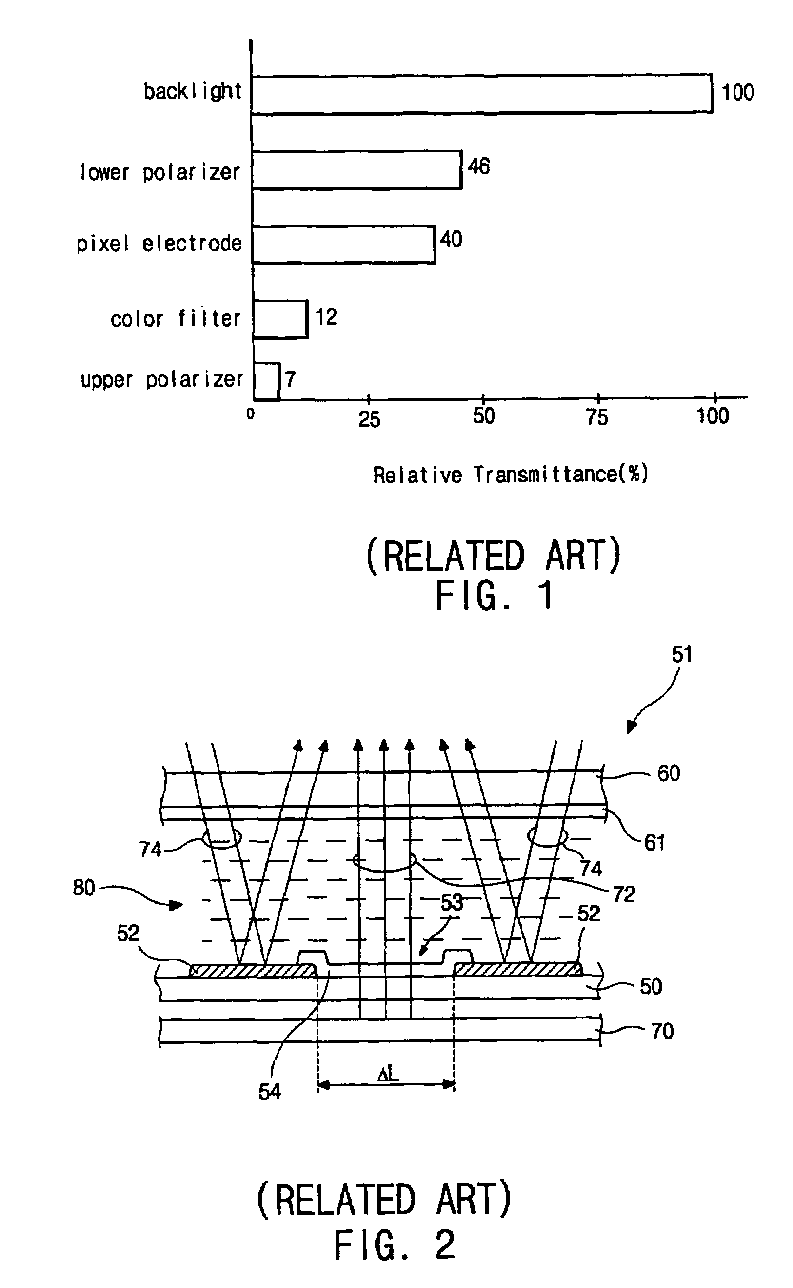
However, the TFT-LCD only employs 3˜8% of the incident light generated from the backlight device, i.e., the inefficient optical modulation.
For this reason, the transmissive TFT-LCD device requires a high, initial brightness, thereby increasing electric power consumption of the backlight device.
Moreover, there still exists a problem that the battery cannot be used for a long time.
Additionally, the reflective TFT-LCD device has a problem that it is affected by its surroundings.
Therefore, the reflective TFT-LCD device cannot be used at night without ambient light.
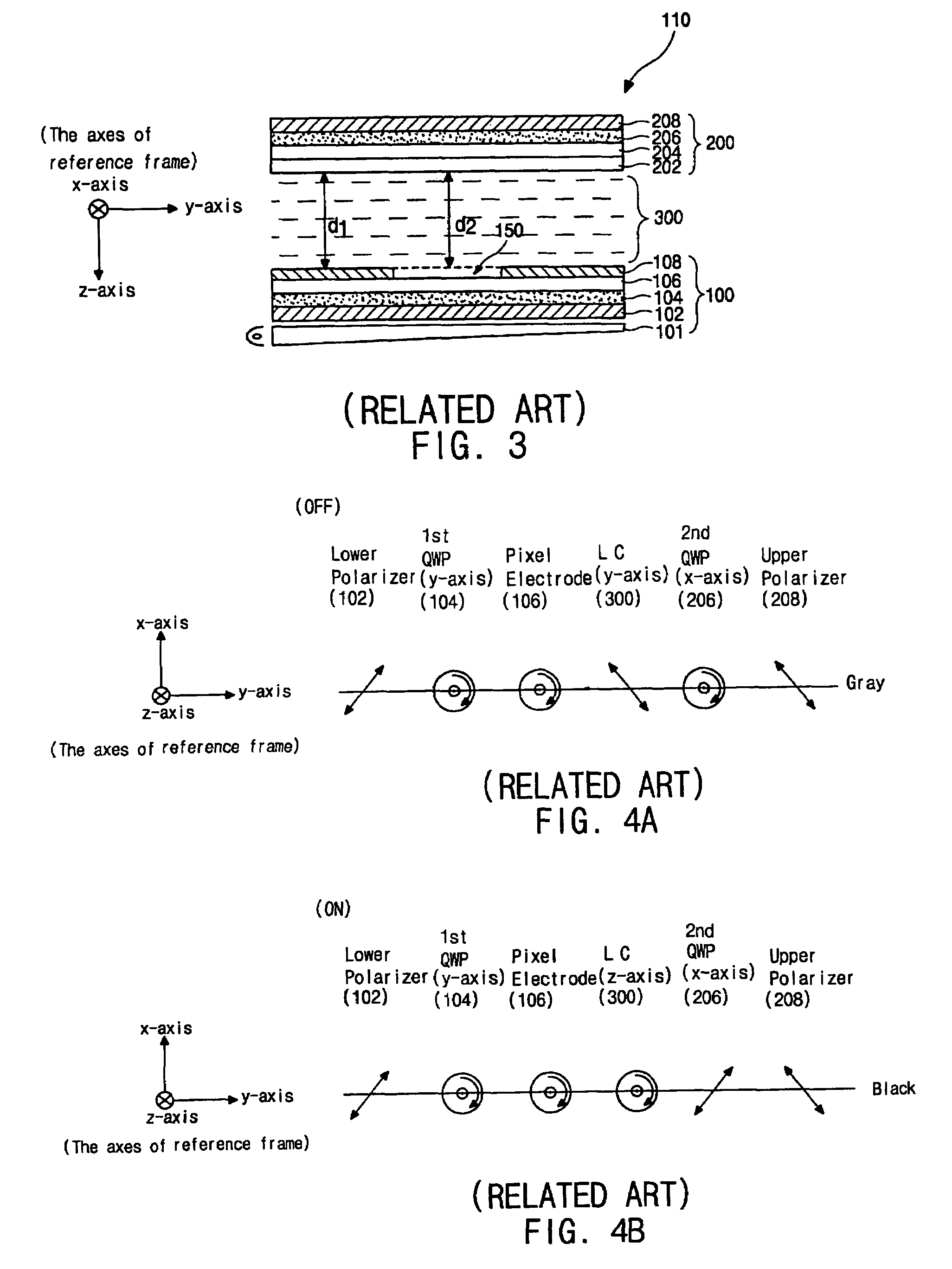
Thus, the transflective LCD device cannot produce the pure white color when the signal voltage is not applied.
Therefore, the conventional LCD device does not properly control the ON / OFF-switch of the blue wavelength band or the red wavelength band.

Method used


Image

  • Transflective liquid crystal display device with particular angle relationships between the half wave plate and polarizers
  • Transflective liquid crystal display device with particular angle relationships between the half wave plate and polarizers
  • Transflective liquid crystal display device with particular angle relationships between the half wave plate and polarizers

Examples


Embodiment Construction

[0052]Reference will now be made in detail to the preferred embodiment of the present invention, example of which is illustrated in the accompanying drawings.

[0053]FIG. 6 is a cross-sectional view of a transflective LCD device according to an embodiment of the present invention. The color filters are not depicted in FIG. 6 because it does not affect the polarization state of the light. As shown, the transflective LCD device 401 is widely divided into a backlight device 700, an array substrate 400, a liquid crystal layer 600, and a color filter substrate 500. The liquid crystal layer 600 affecting polarization state of the light is interposed between the array substrate 400 and the color filter substrate 500. The backlight device 700 is arranged under the lower substrate 400 and emits light into the liquid crystal layer 600.

[0054]The array substrate 400 includes a lower transparent substrate 430, a lower polarizer 410, a transparent conductive electrode 440, a passivation layer 450 a...


PUM


Abstract

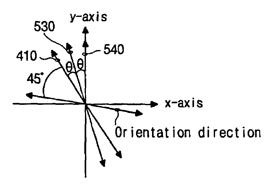
A transflective LCD device improves a light transmittance in both the transmissive mode and the reflective mode and improves efficiency in the use of the light regardless of wavelength. To properly control the ON / OFF-switch of the blue wavelength band or the red wavelength band, the transflective LCD device adopts a half wave plate (λ / 2) and changes the optic axes of the polarizers and the retardation film.

Description

[0001]This is a divisional of application(s) application Ser. No. 09 / 835,849 filed on Apr. 17, 2001 now U.S. Pat. No. 6,611,306.[0002]This application claims the benefit of Korean Patent Application No. 2000-20117, filed on Apr. 17, 2000, under 35 U.S.C. § 119, the entirety of which is hereby incorporated by reference.BACKGROUND OF THE INVENTION[0003]1. Field of the Invention[0004]The present invention relates to a liquid crystal display (LCD) device, and more particularly, to a transflective LCD device that has a high brightness.[0005]2. Description of Related Art[0006]Until now, the cathode-ray tube (CRT) has been developed for and is used mainly for the display systems. However, the flat panel display is beginning to make its appearance due to the requirements of small depth dimensions, undesirably low weight and low voltage power supply. At present, the thin film transistor-liquid crystal display (TFT-LCD) with high resolution and small depth dimension has been developed.[0007]D...

Claims


Application Information

Patent Timeline
IPC IPC(8): G02F1/1335G02F1/133
CPCG02F1/133555G02F1/133371G02F2001/133638G02F1/133638G02F1/133
Inventor BAEK, HEUM-IL
Owner LG DISPLAY CO LTD
Learn More