
Ultra-linear signal processing for radar and laser radar

a laser radar and ultra-linear signal technology, applied in the field of signal processing, can solve the problems of time delay between, unmet needs, and reduce the accuracy of frequency or phase measurement of sinusoid, and achieve the effect of more accurate range measuremen

Active Publication Date: 2007-12-11
THE BOEING CO
View PDF4 Cites 19 Cited by
  • Summary
  • Abstract
  • Description
  • Claims
  • Application Information

AI Technical Summary

Benefits of technology

The present invention provides a system, method, and computer program product for accurately measuring frequency-and / or-phase-related parameters of a sinusoidal signal that varies non-linearly in frequency or phase. This allows for more accurate range measurements than previous methods. The system samples the signal over a finite period of time and performs a Fourier transform on the sampled signals to extract the phase information. The phase information is then used to determine the frequency of the signal. The system also performs pre-processing on the sampled signals, including filtering and adding sample points, to improve the accuracy of the measurements. The invention can be used to determine range to a target by comparing the phase or frequency of the signal with a reference signal.

Problems solved by technology

In an FMCW radar, there is a time delay between the time when the signal is sent to an object and the time when the radiation scattered from the object is collected.
The broad peak reduces accuracy of measurement of frequency or phase of the sinusoid.
However, there is an unmet need in the art for a system and method for accommodating wandering in frequency or phase to permit accurately measuring frequency-and / or-phase-related parameters of a laser radar signal.

Method used


Image

  • Ultra-linear signal processing for radar and laser radar
  • Ultra-linear signal processing for radar and laser radar
  • Ultra-linear signal processing for radar and laser radar

Examples


Embodiment Construction

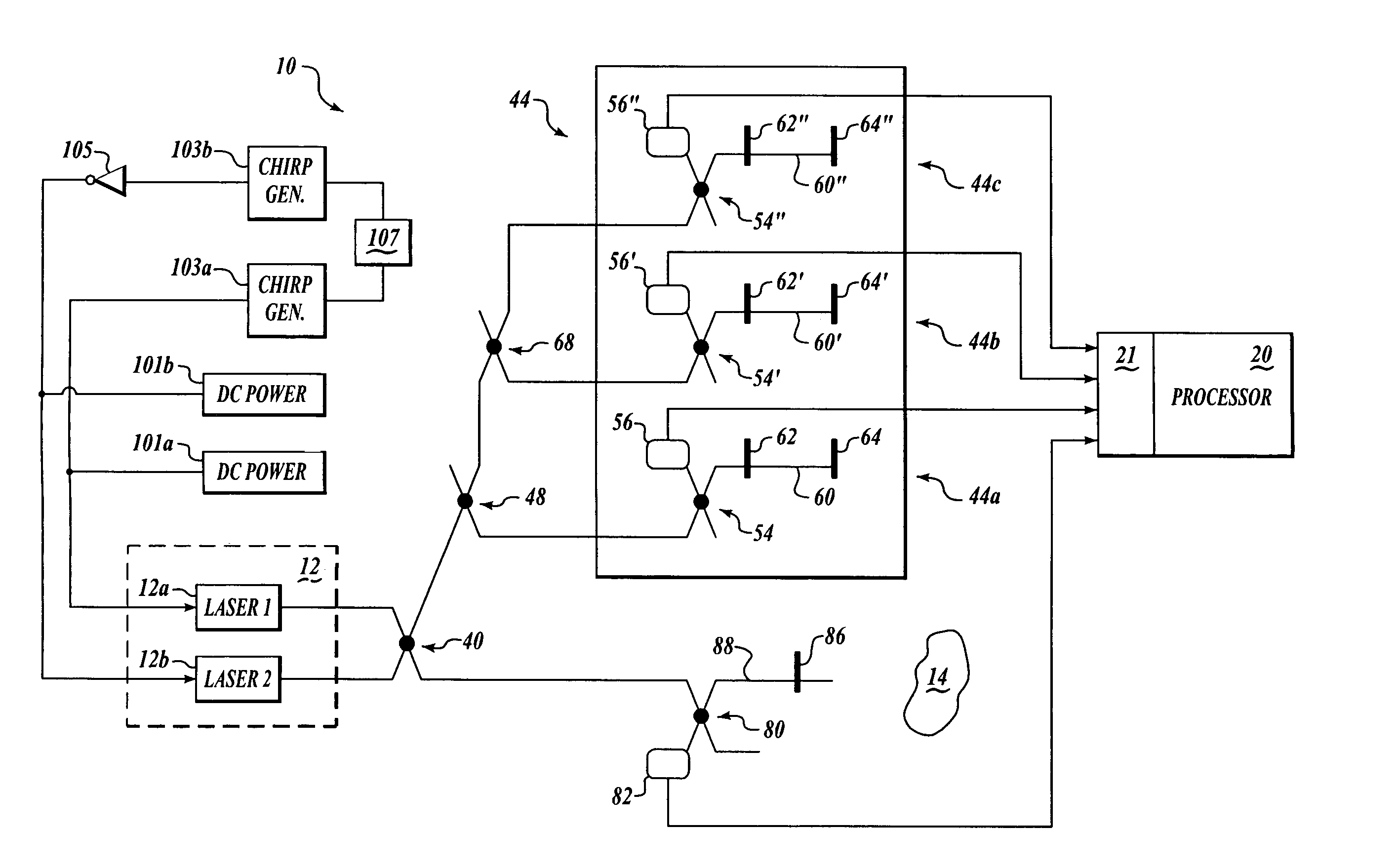
[0019]Embodiments of the present invention provide a system, method, and computer program product for enabling accurate measurement of frequency-and / or-phase-related parameters of a sinusoidal signal that varies non-linearly in frequency or phase. Advantageously, according to other embodiments of the present invention, measurements of frequency and / or phase of such a sinusoidal signal are used to determine range to a target. As a result, embodiments of the present invention are able to provide more accurate range measurements than have been possible in the prior art.

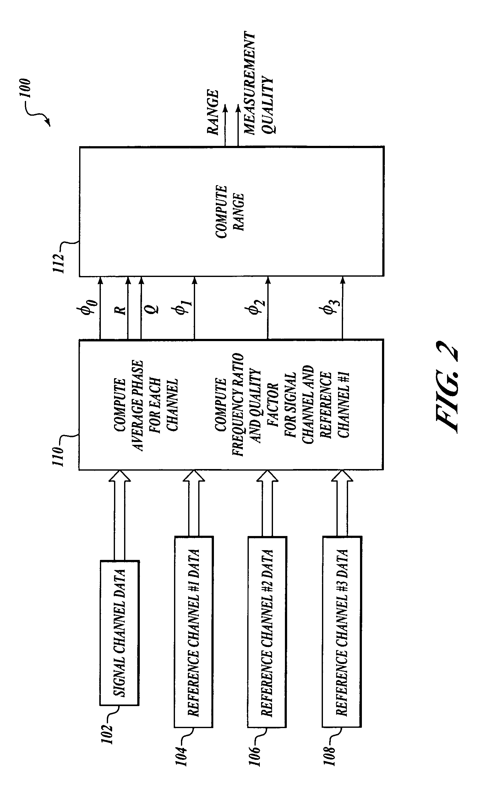
[0020]An exemplary system environment suitable for determining range to a target will first be explained. Next, details will be set forth regarding exemplary signal processing that can accurately measure phase-and / or-frequency-related parameters of a sinusoidal signal according to embodiments of the present invention.

Exemplary System Environment

[0021]Referring now to FIG. 1, an exemplary system 10 determines range to a t...


PUM


Abstract

Systems, methods, and computer program products are provided for accurately measuring frequency-and / or-phase-related parameters of a sinusoidal signal that varies non-linearly in frequency or phase. A sinusoidal signal is sampled over a finite period of time at a plurality of sample points. The sampled signals are pre-processed, and a Fourier transform is performed on the pre-processed sampled signals. Phases of the pre-processed sampled signals are extracted from the Fourier transform, and a measurement indicative of frequency of the sinusoidal signal is determined from slope of the phases of the pre-processed sampled signals. Range to a target may be determined using the exemplary signal processing described above on laser radar interference signals.

Description

FIELD OF THE INVENTION[0001]This invention relates generally to signal processing and, more specifically, to systems and methods for processing radar signals.BACKGROUND OF THE INVENTION[0002]Radio detection and ranging (radar) is used to detect, range (that is, determine a distance), and map a wide variety of objects. For example, a weather radar system on an airplane can detect and range rain or other weather events, and a military fire control radar system can detect and track a military target, such as a ship or an aircraft.[0003]Radar can also be used to range and map objects for manufacturing purposes. For example, laser radar is particularly well-suited for manufacturing large-scale objects (such as aircraft) because laser radar allows precise measurement over a large volume. In one approach referred to as a chirped or Frequency Modulated-Continuous Wave (FMCW) radar, the radar frequency is modulated linearly (or nearly linearly).[0004]In an FMCW radar, there is a time delay b...

Claims


Application Information

Patent Timeline
Patent Type & Authority Patents(United States)
IPC IPC(8): G01C3/08
CPCG01R23/16G01S17/325G01S7/497G01S17/34
Inventor LEEP, DAVID A.SOREIDE, DAVID C.BELL, JOHN A.HAGMAN, RONALD L.
Owner THE BOEING CO
Learn More