Method for inspecting input shaft of power steering system

a technology of power steering system and input shaft, which is applied in the direction of cleaning equipment, instruments, transportation and packaging, etc., can solve the problems of reduced reliability, increased inspection cost, and increased inspection cost, and achieve the effect of accurate inspection

Inactive Publication Date: 2007-12-11
SNU PRECISION CO LTD
View PDF7 Cites 9 Cited by
  • Summary
  • Abstract
  • Description
  • Claims
  • Application Information

AI Technical Summary

Benefits of technology

[0007]The present invention is conceived to solve the aforementioned problems in the prior art. An object of the present invention is to provide a machine and method for inspecting an input shaft for use in a power steering system, wherein the machining precision of the input shaft of the power steering system can be accurately inspected.
[0008]Another object of the present invention is to provide a machine and method for inspecting an input shaft for use in a power steering system, wherein a total inspection for input shafts can be rapidly and accurately made by automating a series of inspection processes such as the feeding, cleaning, sorting, and discharge of the input shafts.
[0009]A further object of the present invention is to provide a machine and method for inspecting an input shaft for use in a power steering system, wherein data on inspection results for the input shaft can be processed and managed in real time.

Problems solved by technology

These shocks become sources of noise and vibration.
Accordingly, some problems involved with a reduction in reliability may be produced.
However, visual inspections that relied entirely upon the determination of the inspector may vary greatly according to measuring errors inherent to the respective inspectors.
Thus, there is a problem in that time and manpower are greatly consumed.
In particular, the sampling inspection is involved with a problem in that reliability for all the input shafts cannot be completely guaranteed.
However, a machine for correctly and rapidly performing a total inspection for input shafts has not yet been developed and thus the total inspection of input shafts cannot be performed using the prior art.

Method used


Image

  • Method for inspecting input shaft of power steering system
  • Method for inspecting input shaft of power steering system
  • Method for inspecting input shaft of power steering system

Examples


Embodiment Construction

[0023]Hereinafter, a preferred embodiment of a machine and method for inspecting an input shaft for use in a power steering system according to the present invention will be described in detail with reference to the accompanying drawings.

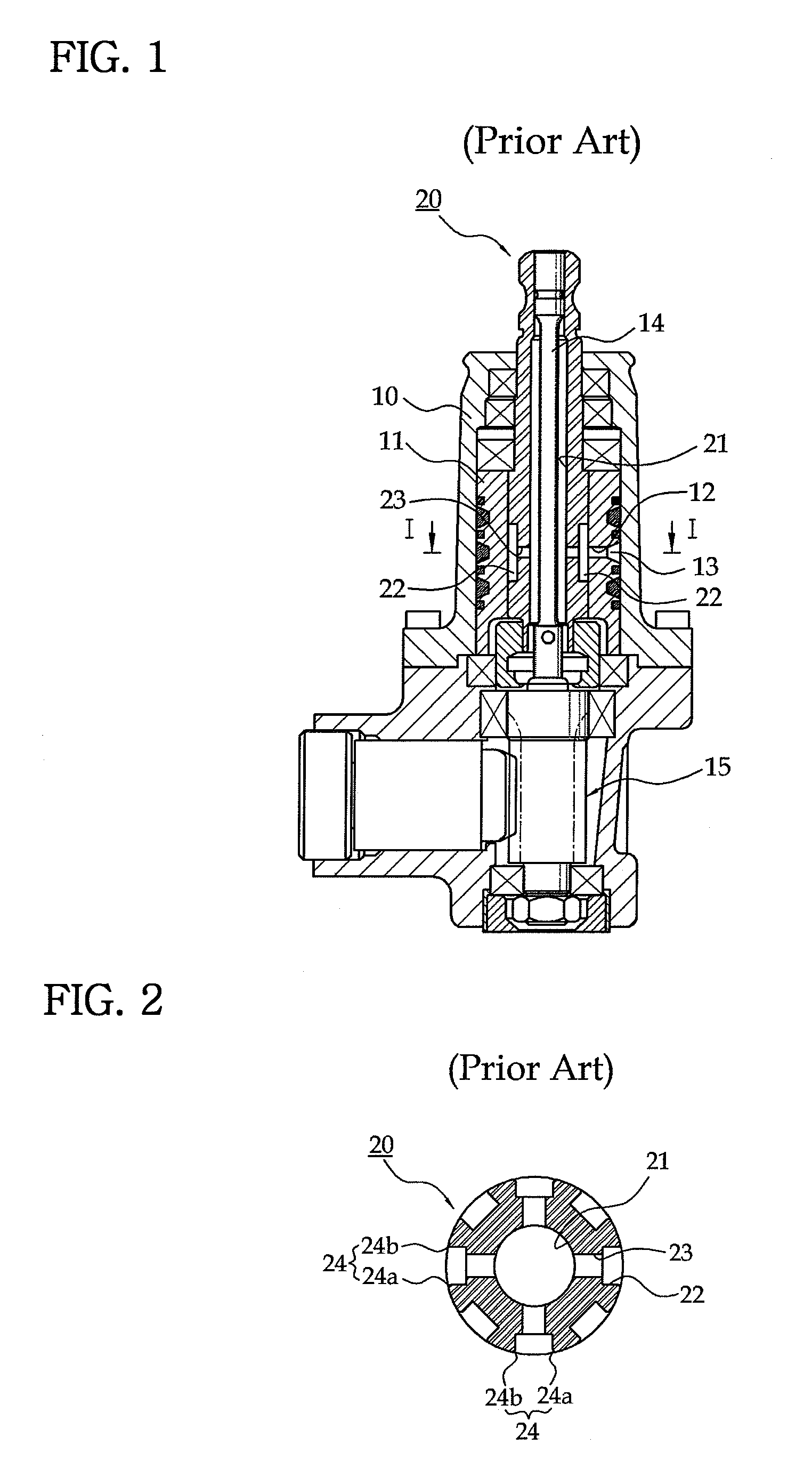
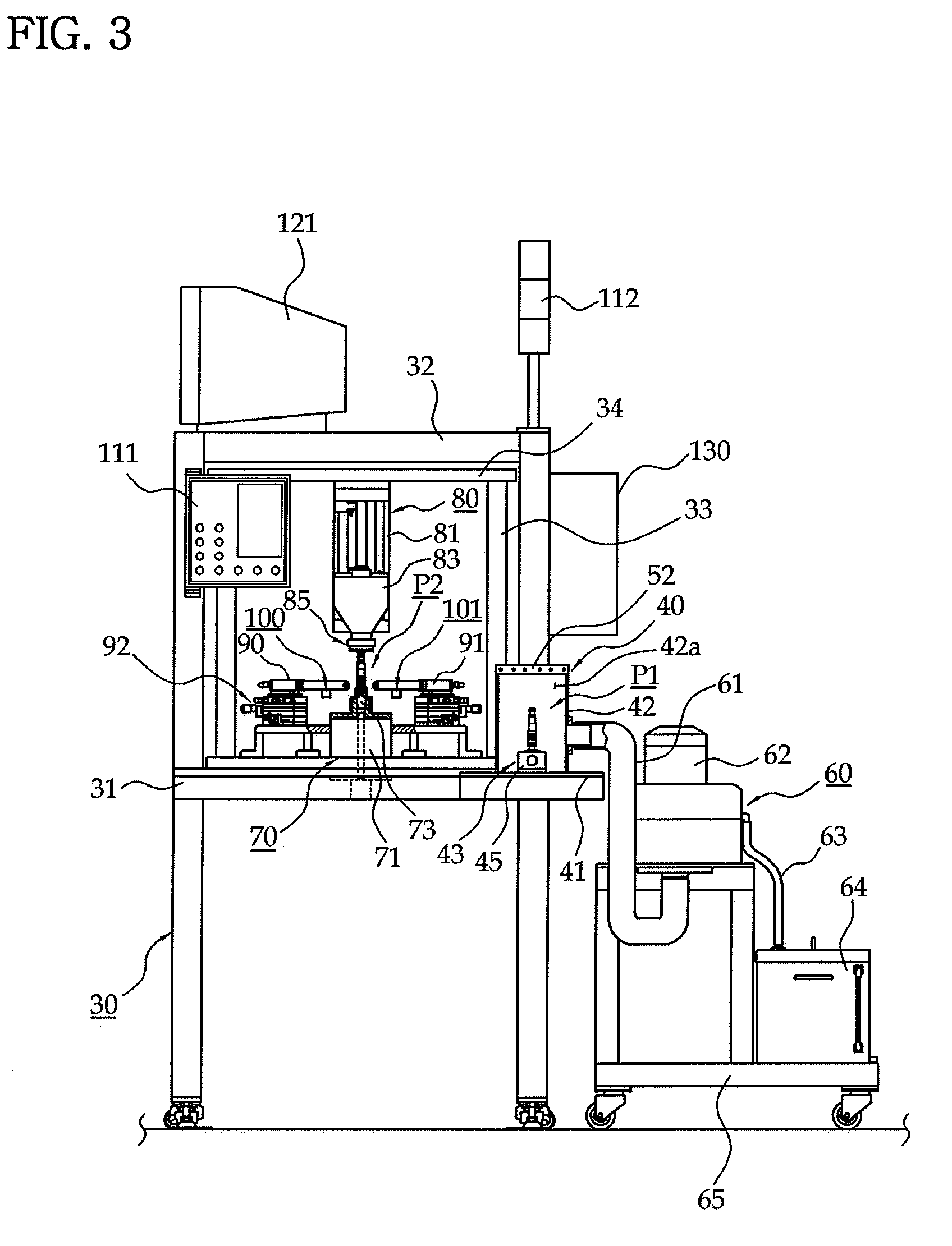
[0024]Referring first to FIGS. 2 and 3, the machine for inspecting an input shaft 20 according to the present invention is arranged in series with a well-known edge-grinding machine for machining chamfers 24 of the input shaft 20. A frame 30 constituting the main body of the machine comprises a worktable 31 on which a cleaning position P1 and an inspecting position P2 of the input shaft 20 are provided, and an overhead frame 32 installed above the worktable 31. A mounting plate 34 is supported by posts 33 and installed below the overhead frame 32. FIG. 3 shows that the cleaning position P1 is on the left side of the worktable 31 whereas the inspecting position P2 is in the middle of the worktable 31 and the overhead frame 32. However, this is a simp...


PUM


Abstract

Provided is a machine and a method for inspecting an input shaft of a power system. First an second cameras take a photograph of first and second champer of the input shaft from directions perpendicular to the chamfers to capture image data of the chamfers. The input shaft is rotated by an indexing drive until overlapping a central line of first and second chamfers of an input shaft on a standard line of image array coordinate system of a computer. Then, widths of the first and second chamfers of the input shaft is calculated. Thereafter, the indexing drive rotates the input shaft by predetermined degrees. The computer processes image data of another first and second chamfers captured by the first and second cameras and calculates widths of the another first and second chamfers. Continuously, widths of remaining chamfers of the input shaft are calculated.

Description

TECHNICAL FIELD[0001]The present invention relates to a machine and method for inspecting an input shaft for use in a power steering system of an automobile, wherein the machining precision of the input shaft for use in the power steering system can be accurately inspected.BACKGROUND ART[0002]As is well known in the art, the power steering system of an automobile is an apparatus for supplying steering oil to a power cylinder cooperating with the steering system by an oil pump driven by engine power so as to facilitate operating a steering wheel. The power steering system is designed in such a manner that large hydraulic pressure is produced when parking or driving a car at a low speed, whereas small hydraulic pressure is produced therein to secure safety when driving a car at a high speed.[0003]An example of such a power steering system will be described with reference to FIGS. 1 and 2. Referring to these figures, a valve body 11 is mounted within a valve housing 10, and a port 12 a...

Claims


Application Information

Patent Timeline
Patent Type & Authority Patents(United States)
IPC IPC(8): G06K9/46G01B11/02B62D5/083G01B11/00G01B11/30G01M13/02
CPCG01B11/00G01B11/30
Inventor PAHK, HEUI-JAEHWANG, MOON-TAEKIM, JIN-KI
Owner SNU PRECISION CO LTD
Why Eureka
Try Eureka