Magnetic bead manipulation and transport device

a technology for magnetic beads and transport devices, which is applied in the direction of electrostatic separation, water/sewage treatment by ion exchange, chemical/physical processes, etc., can solve the problems of cumbersome generating a ‘moving field’, difficult task for manipulating these beads in general and transport in particular, and achieves the effect of higher speed

Inactive Publication Date: 2007-12-18
ECOLE POLYTECHNIQUE FEDERALE DE LAUSANNE (EPFL)
View PDF9 Cites 21 Cited by
  • Summary
  • Abstract
  • Description
  • Claims
  • Application Information

AI Technical Summary

Benefits of technology

[0012]An object of the invention is to provide a device for manipulating and / or transporting microbeads employing simple planar coils which generate low magnetic fields to displace microbeads through longer distances at higher speeds than were heretofore possible.
[0013]A further object of the invention is provide such a device employing simple technology, notably Printed Circuit Board (PCB) technology for the manufacture of the coils, together with simple permanent magnets or electromagnets.

Problems solved by technology

With this proposal, the microbeads were retained and separated by action of a magnetic field generated by the coil, but it was not possible to transport the beads by the action of the magnetic field.
Nevertheless, manipulation of these beads in general and transport in particular, is a difficult task, as the effective relative magnetic susceptibility χeff of the (super)paramagnetic beads is rather weak (typically χeff<<1, due to demagnetization effects of the mostly spherical particles) and the magnetic volume of the particles is small.
This disadvantage is particularly serious for application in biotechnology, where it is desirable to rapidly transport beads over distances of several millimetres which requires several hundreds of actuation steps with this serpentine wire arrangement.
A permanent magnet hence delivers a large force, but the problem is that it is cumbersome in generating a ‘moving’ field.
The consequence is that magnetic forces of coils can be easily varied in space and time but that the forces are too small to effectively transport the microbeads.
However, the prior art does not disclose any effective way of using simple coils to displace magnetic beads.

Method used


Image

  • Magnetic bead manipulation and transport device
  • Magnetic bead manipulation and transport device
  • Magnetic bead manipulation and transport device

Examples


Embodiment Construction

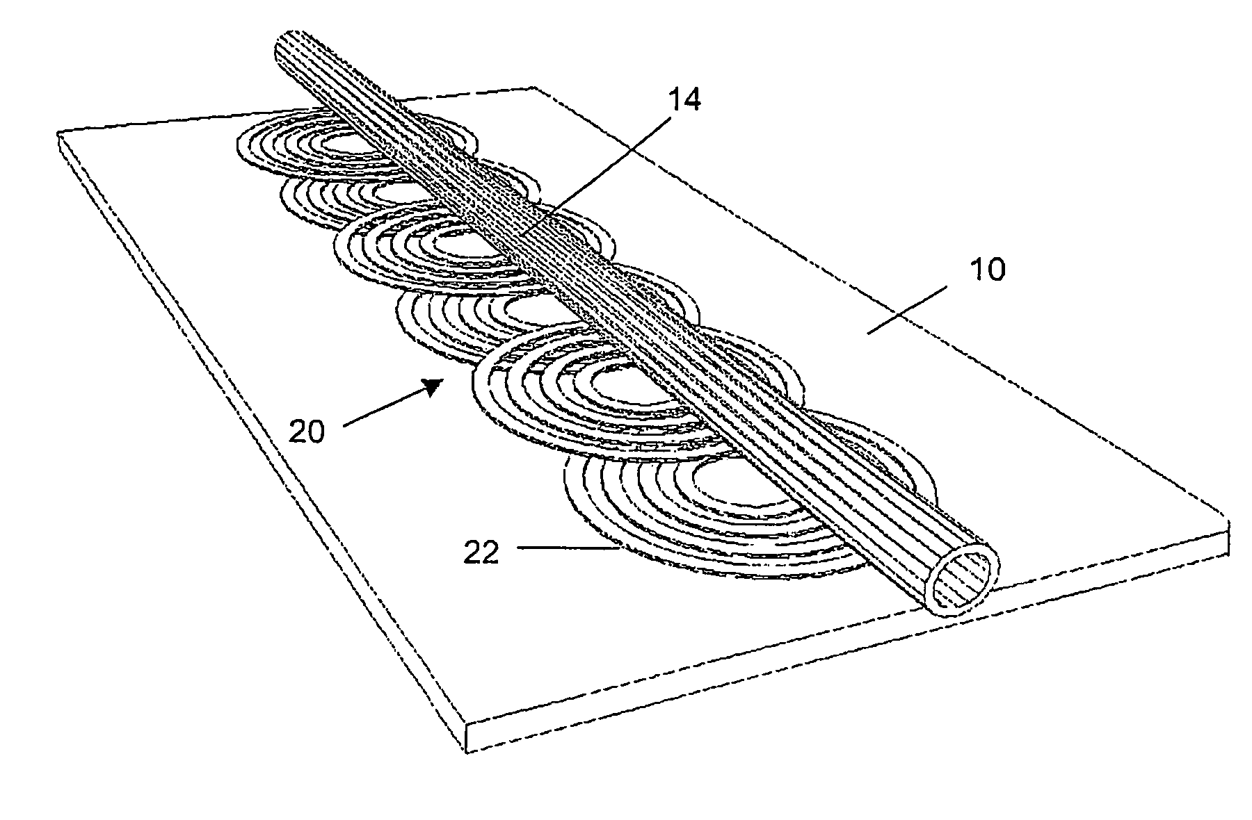
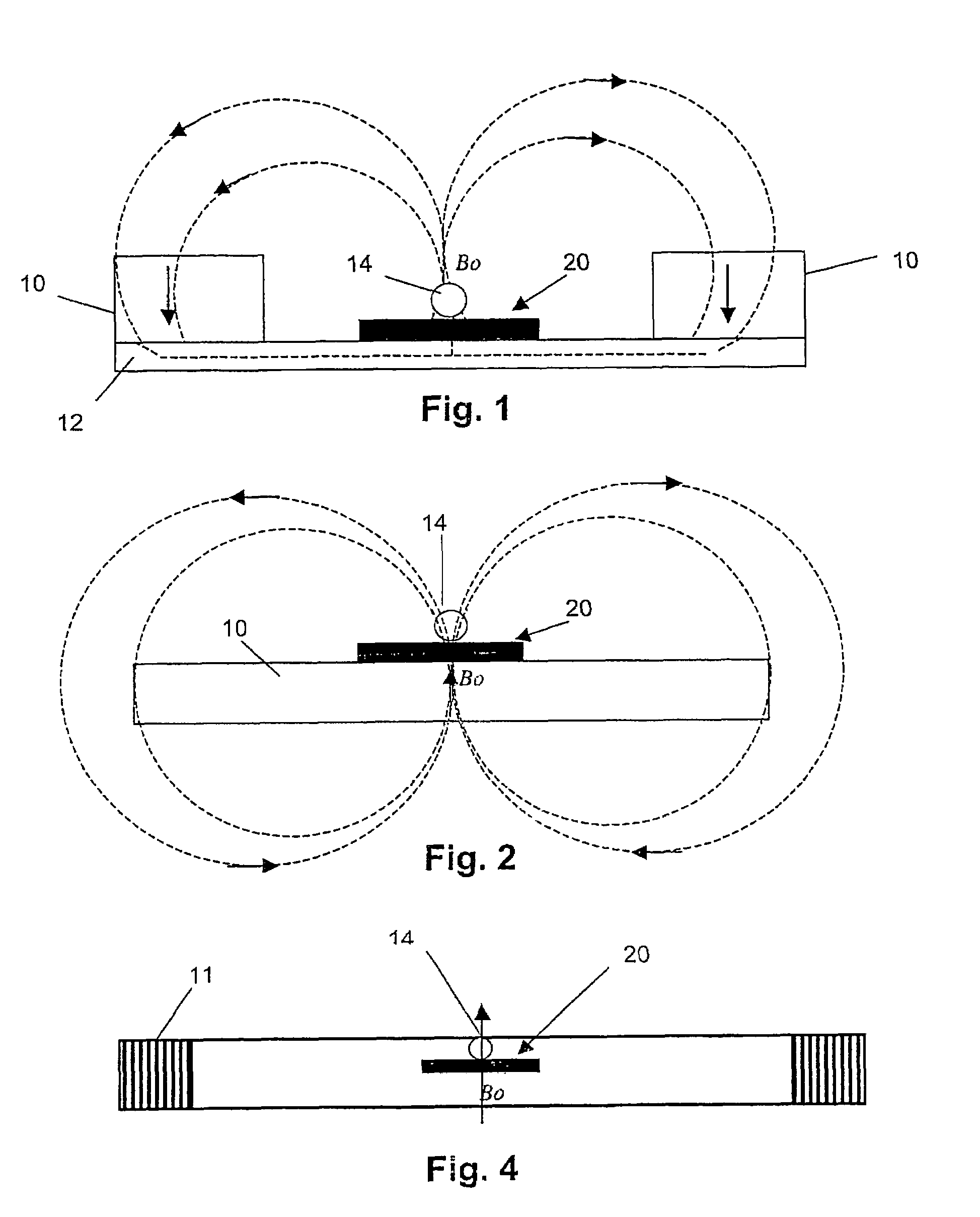
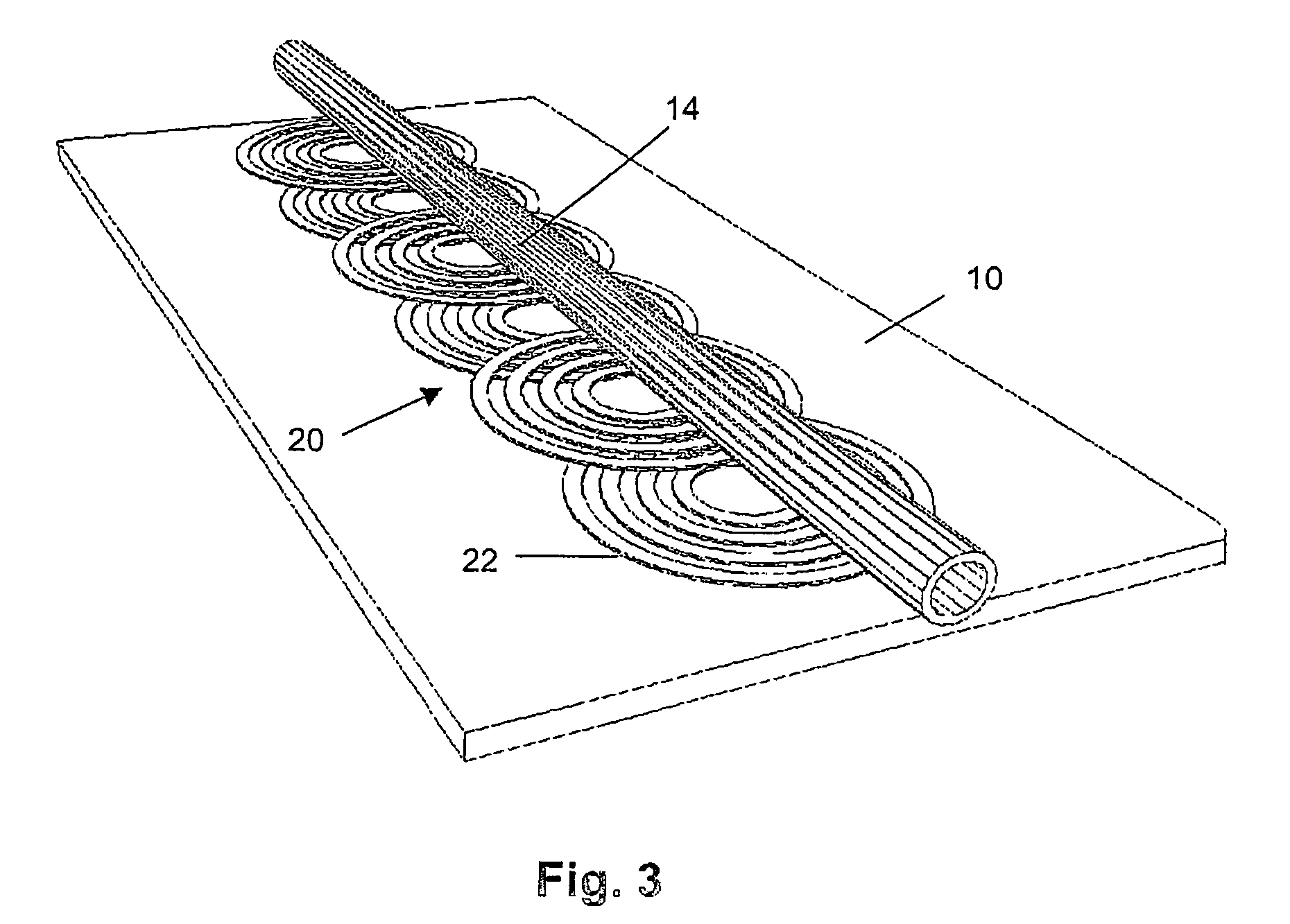
[0037]A first example of a bead transport structure according to the invention is shown in schematic lateral view in FIG. 1. Two bar-shaped NdFeB permanent magnets 10, for example measuring 40 mm×15 mm×8 mm, are placed on top of a soft magnetic sheet 12, and generate a uniform field B0 (for instance 50 mT) over the total length of a microfluidic glass capillary 14, for instance 1 mm outer diameter, 0.5 mm inner diameter. A coil array 20 is positioned on the magnetic sheet 12 directly underneath the capillary 14.

[0038]The capillary 14 contains microbeads in a suitable fluid, for example water. The microbeads typically have dimensions from 0.01 to 10 μm and can be suspended in water and injected in the capillary 14. They can for example be made of Fe3O4. Different types of suitable particles and coatings are listed in WO99 / 49319. An example of suitable magnetic microbeads are Streptavidine MagneSphere® Paramagnetic Particles available from Promega Corporation, Madison, USA. Such parti...


PUM

PropertyMeasurementUnit
distancesaaaaaaaaaa
magnetic fieldaaaaaaaaaa
displacementaaaaaaaaaa

Abstract

A device for transporting magnetic or magnetizable microbeads (25) in a capillary chamber (14) comprises a permanent magnet (10) or an electromagnet (11) for subjecting the capillary chamber to a substantially uniform magnetic field, to apply a permanent magnetic moment to the microbeads (25). At least one planar coil (22) and preferably an array of overlapping coils are located adjacent to the capillary chamber (14) for applying a complementary magnetic field on the microbeads parallel or antiparallel to said substantially uniform magnetic field, to drive the microbeads. An arrangement is provided for switching the current applied to the coil(s) (22) to invert the field produced thereby, to selectively apply an attractive or repulsive driving force on the microbeads (25). The device is usable to transport microbeads for performing chemical and biochemical reactions or assay, as is done for instance in clinical chemistry assays for medical diagnostic purposes.

Description

CROSS REFERENCE TO RELATED APPLICATIONS[0001]This application is a Continuation application of PCT / IB03 / 000956 filed Mar. 8, 2003, which is included in its entirety by reference made hereto.FIELD OF THE INVENTION[0002]This invention relates to devices for manipulation and transport of magnetic beads. The invention concerns in particular an apparatus of the above-mentioned kinds wherein the magnetic beads are used for performing chemical and biochemical reactions or assays, as is done for instance in clinical chemistry for medical diagnostic purposes.BACKGROUND OF THE INVENTION[0003]It is known that magnetic particles (‘beads’) embedded in a liquid can be used to carry a probe molecule on their surface that specifically interacts with a complementary target molecule (for example single stranded probe DNA interacting with complementary target DNA). Upon reaction with a molecule to be probed and, for example, using optical or electrochemical measurements, one can determine the amount o...

Claims


Application Information

Patent Timeline
Patent Type & Authority Patents(United States)
IPC IPC(8): B01D35/06G01N33/553B01F13/00B01F13/08B01L3/00B03C1/035B03C1/28C02F1/48G01N35/00
CPCB01F13/0059B01L3/502761B03C1/035B03C1/288G01N27/745B01F13/0818Y10T436/2575B01F2215/0037B01L2200/0647B01L2300/0816B01L2300/0838B01L2400/0406B01L2400/043G01N2035/00574G01N35/0098B03C2201/26B01F33/30B01F33/452B01F2101/23
Inventor FERNANDEZ, VICTORRIDA, AMARGIJS, MARTIN
Owner ECOLE POLYTECHNIQUE FEDERALE DE LAUSANNE (EPFL)
Why Eureka
Try Eureka